Cisco NME-16ES-1G User Guide - Page 30
Understanding Quality of Service QoS
 |
UPC - 882658036101
View all Cisco NME-16ES-1G manuals
Add to My Manuals
Save this manual to your list of manuals |
Page 30 highlights
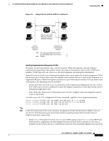
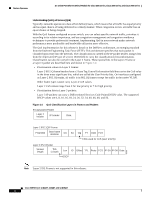
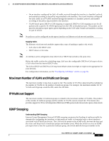
Feature Overview 16- and 36-Port Ethernet Switch Module for Cisco 2600 Series, Cisco 3600 Series, and Cisco 3700 Series Understanding Quality of Service (QoS) Typically, networks operate on a best-effort delivery basis, which means that all traffic has equal priority and an equal chance of being delivered in a timely manner. When congestion occurs, all traffic has an equal chance of being dropped. With the QoS feature configured on your switch, you can select specific network traffic, prioritize it according to its relative importance, and use congestion-management and congestion-avoidance techniques to provide preferential treatment. Implementing QoS in your network makes network performance more predictable and bandwidth utilization more effective. The QoS implementation for this release is based on the DiffServ architecture, an emerging standard from the Internet Engineering Task Force (IETF). This architecture specifies that each packet is classified upon entry into the network. The classification is carried in the IP packet header, using 6 bits from the deprecated IP type of service (ToS) field to carry the classification (class) information. Classification can also be carried in the Layer 2 frame. These special bits in the Layer 2 frame or a Layer 3 packet are described here and shown in Figure 14: • Prioritization values in Layer 2 frames: Layer 2 802.1Q frame headers have a 2-byte Tag Control Information field that carries the CoS value in the three most-significant bits, which are called the User Priority bits. On interfaces configured as Layer 2 802.1Q trunks, all traffic is in 802.1Q frames except for traffic in the native VLAN. Other frame types cannot carry Layer 2 CoS values. Layer 2 CoS values range from 0 for low priority to 7 for high priority. • Prioritization bits in Layer 3 packets: Layer 3 IP packets can carry a Differentiated Services Code Point (DSCP) value. The supported DSCP values are 0, 8, 10, 16, 18, 24, 26, 32, 34, 40, 46, 48, and 56. Figure 14 QoS Classification Layers in Frames and Packets Encapsulated Packet Layer 2 header IP header Data Layer 2 802.1Q/P Frame Preamble Start frame delimiter DA SA Tag PT Data FCS 3 bits used for CoS (user priority) Layer 3 IPv4 Packet Version length ToS (1 byte) Len ID Offset TTL Proto FCS IP-SA IP-DA Data DSCP 60980 Note Layer 2 ISL Frame is not supported in this release. Cisco IOS Release 12.2(2)XT, 12.2(8)T, and 12.2(15)ZJ 30
-
 1
1 -
2
-
3
-
4
-
5
-
6
-
7
-
8
-
9
-
10
-
11
-
12
-
13
-
14
-
15
-
16
-
17
-
18
-
19
-
20
-
21
-
22
-
23
-
24
-
 25
25 -
 26
26 -
 27
27 -
 28
28 -
 29
29 -
 30
30 -
 31
31 -
 32
32 -
 33
33 -
 34
34 -
 35
35 -
36
-
37
-
38
-
39
-
40
-
41
-
42
-
43
-
44
-
45
-
46
-
47
-
48
-
49
-
50
-
51
-
52
-
53
-
54
-
55
-
56
-
57
-
58
-
59
-
60
-
61
-
62
-
63
-
64
-
65
-
66
-
67
-
68
-
69
-
70
-
71
-
72
-
73
-
74
-
75
-
76
-
77
-
78
-
79
-
80
-
81
-
82
-
83
-
84
-
85
-
86
-
87
-
88
-
89
-
90
-
91
-
92
-
93
-
94
-
95
-
96
-
97
-
98
-
99
-
100
-
101
-
102
-
103
-
104
-
105
-
106
-
107
-
108
-
109
-
110
-
111
-
112
-
113
-
114
-
115
-
116
-
117
-
118
-
119
-
120
-
121
-
122
-
123
-
124
-
125
-
126
-
127
-
128
-
129
-
130
-
131
-
132
-
133
-
134
-
135
-
136
-
137
-
138
-
139
-
140
-
141
-
142
-
143
-
144
-
145
-
146
-
147
-
148
-
149
-
150
-
151
-
152
-
153
-
154
-
155
-
156
-
157
-
158
-
159
-
160
-
161
-
162
-
163
-
164
-
165
-
166
-
167
-
168
-
169
-
170
-
171
-
172
-
173
-
174
-
175
-
176
-
177
-
178
-
179
-
180
-
181
-
182
-
183
-
184
-
185
-
186
-
187
-
188
-
189
-
190
-
191
-
192
-
193
-
194
-
195
-
196
-
197
-
198
-
199
-
200
-
201
-
202
-
203
-
204
-
205
-
206
-
207
-
208
-
209
-
210
-
211
-
212
-
213
-
214
-
215
-
216
-
217
-
218
-
219
-
220
-
221
-
222
-
223
-
224
-
225
-
226
-
227
-
228
-
229
-
230
-
231
-
232
-
233
-
234
-
235
-
236
-
237
-
238
-
239
-
240
-
241
-
242
-
243
-
244
-
245
-
246
 |
 |
