Cisco WS-C2960S-24PD-L Software Guide - Page 155
Configuring MVR, Using MVR in a Multicast Television Application
 |
View all Cisco WS-C2960S-24PD-L manuals
Add to My Manuals
Save this manual to your list of manuals |
Page 155 highlights
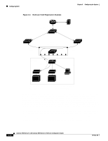
Chapter 6 Configuring the System Configuring MVR Configuring MVR Multicast VLAN Registration (MVR) is designed for applications using wide-scale deployment of multicast traffic (for example, broadcast of multiple television channels) across an Ethernet ring-based service provider network. MVR allows a subscriber on a port to subscribe and unsubscribe to a multicast stream on the network-wide multicast VLAN. It allows the single multicast VLAN to be shared in the network while subscribers remain in separate VLANs. This provides the ability to continuously send multicast streams in the multicast VLAN, but to isolate the streams from the subscriber VLANs for bandwidth and security reasons. MVR assumes that subscriber ports subscribe and unsubscribe (join and leave) these multicast streams by sending out Internet Group Management Protocol (IGMP) join and leave messages. These messages can originate from an IGMP version-2-compatible set-top box with an Ethernet connection or from a PC capable of generating IGMP version-2 messages. The switch CPU identifies IP multicast streams and their associated MAC addresses in the switch forwarding table, intercepts the IGMP messages, and modifies the forwarding table to include or remove the subscriber as a receiver of the multicast stream. This forwarding behavior selectively allows traffic to cross between the two VLANs. Because MVR does not support IGMP dynamic joins, the user or administrator must configure static multicast addresses on the router. Note MVR is supported through the CLI and SNMP. Using MVR in a Multicast Television Application In a multicast television application, a PC or a television with a set-top box can receive the multicast stream. Multiple set-top boxes or PCs can be connected to one subscriber port. (See Figure 6-6.) DHCP assigns an IP address to the set-top box or the PC. When a subscriber selects a channel, the set-top box or PC sends an IGMP report to the access layer switch (S1 switch) to join the appropriate multicast. If the IGMP report matches one of the configured multicast MAC addresses, the switch CPU modifies the hardware address table to include this receiver port and VLAN as a forwarding destination of the specified multicast stream when it is received from the multicast VLAN over the source port. When a subscriber changes channels or turns off the television, the set-top box sends an IGMP leave message for the multicast stream. The switch CPU sends an IGMP group-specific query through the receiver port VLAN. If there is another set-top box in the VLAN still subscribing to this group, that set-top box must respond within the maximum response time. If the CPU does not receive a response, it eliminates the receiver port as a forwarding destination for this group. 78-6511-08 Catalyst 2900 Series XL and Catalyst 3500 Series XL Software Configuration Guide 6-27
-
 1
1 -
2
-
3
-
4
-
5
-
6
-
7
-
8
-
9
-
10
-
11
-
12
-
13
-
14
-
15
-
16
-
17
-
18
-
19
-
20
-
21
-
22
-
23
-
24
-
25
-
26
-
27
-
28
-
29
-
30
-
31
-
32
-
33
-
34
-
35
-
36
-
37
-
38
-
39
-
40
-
41
-
42
-
43
-
44
-
45
-
46
-
47
-
48
-
49
-
50
-
51
-
52
-
53
-
54
-
55
-
56
-
57
-
58
-
59
-
60
-
61
-
62
-
63
-
64
-
65
-
66
-
67
-
68
-
69
-
70
-
71
-
72
-
73
-
74
-
75
-
76
-
77
-
78
-
79
-
80
-
81
-
82
-
83
-
84
-
85
-
86
-
87
-
88
-
89
-
90
-
91
-
92
-
93
-
94
-
95
-
96
-
97
-
98
-
99
-
100
-
101
-
102
-
103
-
104
-
105
-
106
-
107
-
108
-
109
-
110
-
111
-
112
-
113
-
114
-
115
-
116
-
117
-
118
-
119
-
120
-
121
-
122
-
123
-
124
-
125
-
126
-
127
-
128
-
129
-
130
-
131
-
132
-
133
-
134
-
135
-
136
-
137
-
138
-
139
-
140
-
141
-
142
-
143
-
144
-
145
-
146
-
147
-
148
-
149
-
 150
150 -
 151
151 -
 152
152 -
 153
153 -
 154
154 -
 155
155 -
 156
156 -
 157
157 -
 158
158 -
 159
159 -
 160
160 -
161
-
162
-
163
-
164
-
165
-
166
-
167
-
168
-
169
-
170
-
171
-
172
-
173
-
174
-
175
-
176
-
177
-
178
-
179
-
180
-
181
-
182
-
183
-
184
-
185
-
186
-
187
-
188
-
189
-
190
-
191
-
192
-
193
-
194
-
195
-
196
-
197
-
198
-
199
-
200
-
201
-
202
-
203
-
204
-
205
-
206
-
207
-
208
-
209
-
210
-
211
-
212
-
213
-
214
-
215
-
216
-
217
-
218
-
219
-
220
-
221
-
222
-
223
-
224
-
225
-
226
-
227
-
228
-
229
-
230
-
231
-
232
-
233
-
234
-
235
-
236
-
237
-
238
-
239
-
240
-
241
-
242
-
243
-
244
-
245
-
246
-
247
-
248
-
249
-
250
-
251
-
252
-
253
-
254
-
255
-
256
-
257
-
258
-
259
-
260
-
261
-
262
-
263
-
264
-
265
-
266
-
267
-
268
-
269
-
270
-
271
-
272
-
273
-
274
-
275
-
276
-
277
-
278
-
279
-
280
-
281
-
282
-
283
-
284
-
285
-
286
-
287
-
288
-
289
-
290
-
291
-
292
-
293
-
294
-
295
-
296
-
297
-
298
-
299
-
300
-
301
-
302
-
303
-
304
-
305
-
306
-
307
-
308
-
309
-
310
-
311
-
312
-
313
-
314
-
315
-
316
-
317
-
318
-
319
-
320
-
321
-
322
-
323
-
324
-
325
-
326
-
327
-
328
-
329
-
330
-
331
-
332
-
333
-
334
-
335
-
336
-
337
-
338
-
339
-
340
-
341
-
342
-
343
-
344
-
345
-
346
-
347
-
348
-
349
-
350
-
351
-
352
-
353
-
354
-
355
-
356
-
357
-
358
-
359
-
360
-
361
-
362
-
363
-
364
-
365
-
366
-
367
-
368
 |
 |
