Cisco WS-C2960S-24PD-L Software Guide - Page 165
Enabling STP UplinkFast, Configuring Cross-Stack UplinkFast, How CSUF Works
 |
View all Cisco WS-C2960S-24PD-L manuals
Add to My Manuals
Save this manual to your list of manuals |
Page 165 highlights
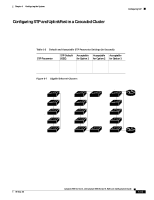
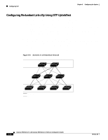
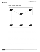
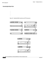
Chapter 6 Configuring the System Configuring STP Enabling STP UplinkFast When you enable UplinkFast, it is enabled for the entire switch and cannot be enabled for individual VLANs. Beginning in privileged EXEC mode, follow these steps to configure UplinkFast: Step 1 Step 2 Command configure terminal spanning-tree uplinkfast max-update-rate pkts-per-second Step 3 exit Step 4 show spanning-tree Purpose Enter global configuration mode. Enable UplinkFast on the switch. The range is from 0 to 1000 packets per second. The default is 150. If you set the rate to 0, station-learning frames are not generated, so the STP topology converges more slowly after a loss of connectivity. Return to privileged EXEC mode. Verify your entries. When UplinkFast is enabled, the bridge priority of all VLANs is set to 49152, and the path cost of all ports and VLAN trunks is increased by 3000. This change reduces the chance that the switch will become the root switch. When UplinkFast is disabled, the bridge priorities of all VLANs and path costs of all ports are set to default values. Configuring Cross-Stack UplinkFast Cross-stack UplinkFast (CSUF) provides a fast spanning-tree transition (fast convergence in less than 2 seconds under normal network conditions) across a stack of switches that use the GigaStack GBICs connected in a shared cascaded configuration (multidrop backbone). During the fast transition, an alternate redundant link on the stack of switches is placed into the forwarding state without causing temporary spanning-tree loops or loss of connectivity to the backbone. With this feature, you can have a redundant and resilient network in some configurations. CSUF might not provide a fast transition all the time; in these cases, the normal STP transition occurs, which completes in 30 to 40 seconds. For more information, see the "Events that Cause Fast Convergence" section on page 6-39. How CSUF Works CSUF ensures that one link in the stack is elected as the path to the root. As shown in Figure 6-9, Switches A, B, and C are cascaded through the Gigastack GBIC to form a multidrop backbone, which communicates control and data traffic across the switches at the access layer. The switches in the stack use their stack ports to communicate with each other and to connect to the stack backbone; stack ports are always in the STP forwarding state. The stack root port on Switch A provides the path to the root of the spanning tree; the alternate stack root ports on Switches B and C can provide an alternate path to the spanning-tree root if the current stack root switch fails or its link to the spanning-tree root fails. Link A, the root link, is in the STP forwarding state; Links B and C are alternate redundant links that are in the STP blocking state. If Switch A fails, if its stack root port fails, or if Link A fails, CSUF selects either the Switch B or Switch C alternate stack root port and puts it into the forwarding state in less than 1 second. 78-6511-08 Catalyst 2900 Series XL and Catalyst 3500 Series XL Software Configuration Guide 6-37
-
 1
1 -
2
-
3
-
4
-
5
-
6
-
7
-
8
-
9
-
10
-
11
-
12
-
13
-
14
-
15
-
16
-
17
-
18
-
19
-
20
-
21
-
22
-
23
-
24
-
25
-
26
-
27
-
28
-
29
-
30
-
31
-
32
-
33
-
34
-
35
-
36
-
37
-
38
-
39
-
40
-
41
-
42
-
43
-
44
-
45
-
46
-
47
-
48
-
49
-
50
-
51
-
52
-
53
-
54
-
55
-
56
-
57
-
58
-
59
-
60
-
61
-
62
-
63
-
64
-
65
-
66
-
67
-
68
-
69
-
70
-
71
-
72
-
73
-
74
-
75
-
76
-
77
-
78
-
79
-
80
-
81
-
82
-
83
-
84
-
85
-
86
-
87
-
88
-
89
-
90
-
91
-
92
-
93
-
94
-
95
-
96
-
97
-
98
-
99
-
100
-
101
-
102
-
103
-
104
-
105
-
106
-
107
-
108
-
109
-
110
-
111
-
112
-
113
-
114
-
115
-
116
-
117
-
118
-
119
-
120
-
121
-
122
-
123
-
124
-
125
-
126
-
127
-
128
-
129
-
130
-
131
-
132
-
133
-
134
-
135
-
136
-
137
-
138
-
139
-
140
-
141
-
142
-
143
-
144
-
145
-
146
-
147
-
148
-
149
-
150
-
151
-
152
-
153
-
154
-
155
-
156
-
157
-
158
-
159
-
 160
160 -
 161
161 -
 162
162 -
 163
163 -
 164
164 -
 165
165 -
 166
166 -
 167
167 -
 168
168 -
 169
169 -
 170
170 -
171
-
172
-
173
-
174
-
175
-
176
-
177
-
178
-
179
-
180
-
181
-
182
-
183
-
184
-
185
-
186
-
187
-
188
-
189
-
190
-
191
-
192
-
193
-
194
-
195
-
196
-
197
-
198
-
199
-
200
-
201
-
202
-
203
-
204
-
205
-
206
-
207
-
208
-
209
-
210
-
211
-
212
-
213
-
214
-
215
-
216
-
217
-
218
-
219
-
220
-
221
-
222
-
223
-
224
-
225
-
226
-
227
-
228
-
229
-
230
-
231
-
232
-
233
-
234
-
235
-
236
-
237
-
238
-
239
-
240
-
241
-
242
-
243
-
244
-
245
-
246
-
247
-
248
-
249
-
250
-
251
-
252
-
253
-
254
-
255
-
256
-
257
-
258
-
259
-
260
-
261
-
262
-
263
-
264
-
265
-
266
-
267
-
268
-
269
-
270
-
271
-
272
-
273
-
274
-
275
-
276
-
277
-
278
-
279
-
280
-
281
-
282
-
283
-
284
-
285
-
286
-
287
-
288
-
289
-
290
-
291
-
292
-
293
-
294
-
295
-
296
-
297
-
298
-
299
-
300
-
301
-
302
-
303
-
304
-
305
-
306
-
307
-
308
-
309
-
310
-
311
-
312
-
313
-
314
-
315
-
316
-
317
-
318
-
319
-
320
-
321
-
322
-
323
-
324
-
325
-
326
-
327
-
328
-
329
-
330
-
331
-
332
-
333
-
334
-
335
-
336
-
337
-
338
-
339
-
340
-
341
-
342
-
343
-
344
-
345
-
346
-
347
-
348
-
349
-
350
-
351
-
352
-
353
-
354
-
355
-
356
-
357
-
358
-
359
-
360
-
361
-
362
-
363
-
364
-
365
-
366
-
367
-
368
 |
 |
