Cisco WS-C2960S-24PD-L Software Guide - Page 247
Deleting a VLAN from the Database, Assigning Static-Access Ports to a VLAN
 |
View all Cisco WS-C2960S-24PD-L manuals
Add to My Manuals
Save this manual to your list of manuals |
Page 247 highlights
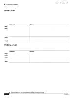
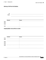
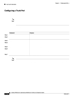
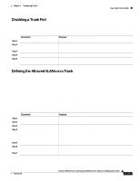
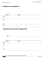
Chapter 8 Configuring VLANs VLANs in the VTP Database Deleting a VLAN from the Database When you delete a VLAN from a switch that is in VTP server mode, the VLAN is removed from all switches in the VTP domain. When you delete a VLAN from a switch that is in VTP transparent mode, the VLAN is deleted only on that specific switch. You cannot delete the default VLANs for the different media types: Ethernet VLAN 1 and FDDI or Token Ring VLANs 1002 to 1005. Caution When you delete a VLAN, any ports assigned to that VLAN become inactive. They remain associated with the VLAN (and thus inactive) until you assign them to a new VLAN. Beginning in privileged EXEC mode, follow these steps to delete a VLAN on the switch: Step 1 Step 2 Step 3 Command vlan database no vlan vlan-id exit Step 4 show vlan brief Purpose Enter VLAN configuration mode. Remove the VLAN by using the VLAN ID. Update the VLAN database, propagate it throughout the administrative domain, and return to privileged EXEC mode. Verify the VLAN removal. Assigning Static-Access Ports to a VLAN By default, all ports are static-access ports assigned to VLAN 1, which is the default management VLAN. If you are assigning a port on a cluster member switch to a VLAN, first log in to the member switch by using the privileged EXEC rcommand command. For more information on how to use this command, refer to the switch command reference. Beginning in privileged EXEC mode, follow these steps to assign a port to a VLAN in the VTP database: Step 1 Step 2 Command configure terminal interface interface Step 3 Step 4 Step 5 Step 6 switchport mode access switchport access vlan 3 exit show interface interface-id switchport Purpose Enter global configuration mode. Enter interface configuration mode, and define the interface to be added to the VLAN. Define the VLAN membership mode for this port. Assign the port to the VLAN. Return to privileged EXEC mode. Verify the VLAN configuration. In the display, check the Operation Mode, Access Mode VLAN, and the Priority for Untagged Frames fields. 78-6511-08 Catalyst 2900 Series XL and Catalyst 3500 Series XL Software Configuration Guide 8-25
-
 1
1 -
2
-
3
-
4
-
5
-
6
-
7
-
8
-
9
-
10
-
11
-
12
-
13
-
14
-
15
-
16
-
17
-
18
-
19
-
20
-
21
-
22
-
23
-
24
-
25
-
26
-
27
-
28
-
29
-
30
-
31
-
32
-
33
-
34
-
35
-
36
-
37
-
38
-
39
-
40
-
41
-
42
-
43
-
44
-
45
-
46
-
47
-
48
-
49
-
50
-
51
-
52
-
53
-
54
-
55
-
56
-
57
-
58
-
59
-
60
-
61
-
62
-
63
-
64
-
65
-
66
-
67
-
68
-
69
-
70
-
71
-
72
-
73
-
74
-
75
-
76
-
77
-
78
-
79
-
80
-
81
-
82
-
83
-
84
-
85
-
86
-
87
-
88
-
89
-
90
-
91
-
92
-
93
-
94
-
95
-
96
-
97
-
98
-
99
-
100
-
101
-
102
-
103
-
104
-
105
-
106
-
107
-
108
-
109
-
110
-
111
-
112
-
113
-
114
-
115
-
116
-
117
-
118
-
119
-
120
-
121
-
122
-
123
-
124
-
125
-
126
-
127
-
128
-
129
-
130
-
131
-
132
-
133
-
134
-
135
-
136
-
137
-
138
-
139
-
140
-
141
-
142
-
143
-
144
-
145
-
146
-
147
-
148
-
149
-
150
-
151
-
152
-
153
-
154
-
155
-
156
-
157
-
158
-
159
-
160
-
161
-
162
-
163
-
164
-
165
-
166
-
167
-
168
-
169
-
170
-
171
-
172
-
173
-
174
-
175
-
176
-
177
-
178
-
179
-
180
-
181
-
182
-
183
-
184
-
185
-
186
-
187
-
188
-
189
-
190
-
191
-
192
-
193
-
194
-
195
-
196
-
197
-
198
-
199
-
200
-
201
-
202
-
203
-
204
-
205
-
206
-
207
-
208
-
209
-
210
-
211
-
212
-
213
-
214
-
215
-
216
-
217
-
218
-
219
-
220
-
221
-
222
-
223
-
224
-
225
-
226
-
227
-
228
-
229
-
230
-
231
-
232
-
233
-
234
-
235
-
236
-
237
-
238
-
239
-
240
-
241
-
 242
242 -
 243
243 -
 244
244 -
 245
245 -
 246
246 -
 247
247 -
 248
248 -
 249
249 -
 250
250 -
 251
251 -
 252
252 -
253
-
254
-
255
-
256
-
257
-
258
-
259
-
260
-
261
-
262
-
263
-
264
-
265
-
266
-
267
-
268
-
269
-
270
-
271
-
272
-
273
-
274
-
275
-
276
-
277
-
278
-
279
-
280
-
281
-
282
-
283
-
284
-
285
-
286
-
287
-
288
-
289
-
290
-
291
-
292
-
293
-
294
-
295
-
296
-
297
-
298
-
299
-
300
-
301
-
302
-
303
-
304
-
305
-
306
-
307
-
308
-
309
-
310
-
311
-
312
-
313
-
314
-
315
-
316
-
317
-
318
-
319
-
320
-
321
-
322
-
323
-
324
-
325
-
326
-
327
-
328
-
329
-
330
-
331
-
332
-
333
-
334
-
335
-
336
-
337
-
338
-
339
-
340
-
341
-
342
-
343
-
344
-
345
-
346
-
347
-
348
-
349
-
350
-
351
-
352
-
353
-
354
-
355
-
356
-
357
-
358
-
359
-
360
-
361
-
362
-
363
-
364
-
365
-
366
-
367
-
368
 |
 |
