Cisco WS-C2960S-24PD-L Software Guide - Page 156
Multicast VLAN Registration Example
 |
View all Cisco WS-C2960S-24PD-L manuals
Add to My Manuals
Save this manual to your list of manuals |
Page 156 highlights
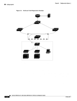
Configuring MVR Chapter 6 Configuring the System Figure 6-6 Multicast VLAN Registration Example Cisco router Catalyst 2900/3500 XL switch SP SP Multicast data Catalyst 2900/3500 XL switch SP SP SP Catalyst 2900/3500 XL SP1 switch S1 Multicast server Catalyst 2900/3500 XL switch SP SP2 Multicast data RP1 RP2 RP3 RP4 RP5 RP6 RP7 Customer premises Hub IGMP join Set-top box TV data Set-top box PC 47849 TV RP = Receiver Port SP = Source Port TV Note: All source ports belong to the multicast VLAN. MVR eliminates the need to duplicate television-channel multicast traffic for subscribers in each VLAN. Multicast traffic for all channels is sent only once around the VLAN trunk-only on the multicast VLAN. Although the IGMP leave and join messages originate with a subscriber, they appear to be initiated by a port in the multicast VLAN rather than in the VLAN to which the subscriber port is assigned. These messages dynamically register for streams of multicast traffic in the multicast VLAN on the switch. The access layer switch (S1 switch) modifies the forwarding behavior to allow the traffic to be forwarded from the multicast VLAN to the subscriber port in a different VLAN, selectively allowing traffic to cross between two VLANs. IGMP reports are sent to the same MAC addresses as the multicast data. The S1 CPU must capture all IGMP join and leave messages from subscriber ports. Because the Catalyst 2900 and Catalyst 3500 hardware cannot distinguish IP multicast data packets from IP multicast packets carrying IGMP protocol data, all packets from subscriber ports destined for the configured multicast MAC addresses are forwarded to the switch CPU, which distinguishes IGMP packets from regular multicast traffic. 6-28 Catalyst 2900 Series XL and Catalyst 3500 Series XL Software Configuration Guide 78-6511-08
-
 1
1 -
2
-
3
-
4
-
5
-
6
-
7
-
8
-
9
-
10
-
11
-
12
-
13
-
14
-
15
-
16
-
17
-
18
-
19
-
20
-
21
-
22
-
23
-
24
-
25
-
26
-
27
-
28
-
29
-
30
-
31
-
32
-
33
-
34
-
35
-
36
-
37
-
38
-
39
-
40
-
41
-
42
-
43
-
44
-
45
-
46
-
47
-
48
-
49
-
50
-
51
-
52
-
53
-
54
-
55
-
56
-
57
-
58
-
59
-
60
-
61
-
62
-
63
-
64
-
65
-
66
-
67
-
68
-
69
-
70
-
71
-
72
-
73
-
74
-
75
-
76
-
77
-
78
-
79
-
80
-
81
-
82
-
83
-
84
-
85
-
86
-
87
-
88
-
89
-
90
-
91
-
92
-
93
-
94
-
95
-
96
-
97
-
98
-
99
-
100
-
101
-
102
-
103
-
104
-
105
-
106
-
107
-
108
-
109
-
110
-
111
-
112
-
113
-
114
-
115
-
116
-
117
-
118
-
119
-
120
-
121
-
122
-
123
-
124
-
125
-
126
-
127
-
128
-
129
-
130
-
131
-
132
-
133
-
134
-
135
-
136
-
137
-
138
-
139
-
140
-
141
-
142
-
143
-
144
-
145
-
146
-
147
-
148
-
149
-
150
-
 151
151 -
 152
152 -
 153
153 -
 154
154 -
 155
155 -
 156
156 -
 157
157 -
 158
158 -
 159
159 -
 160
160 -
 161
161 -
162
-
163
-
164
-
165
-
166
-
167
-
168
-
169
-
170
-
171
-
172
-
173
-
174
-
175
-
176
-
177
-
178
-
179
-
180
-
181
-
182
-
183
-
184
-
185
-
186
-
187
-
188
-
189
-
190
-
191
-
192
-
193
-
194
-
195
-
196
-
197
-
198
-
199
-
200
-
201
-
202
-
203
-
204
-
205
-
206
-
207
-
208
-
209
-
210
-
211
-
212
-
213
-
214
-
215
-
216
-
217
-
218
-
219
-
220
-
221
-
222
-
223
-
224
-
225
-
226
-
227
-
228
-
229
-
230
-
231
-
232
-
233
-
234
-
235
-
236
-
237
-
238
-
239
-
240
-
241
-
242
-
243
-
244
-
245
-
246
-
247
-
248
-
249
-
250
-
251
-
252
-
253
-
254
-
255
-
256
-
257
-
258
-
259
-
260
-
261
-
262
-
263
-
264
-
265
-
266
-
267
-
268
-
269
-
270
-
271
-
272
-
273
-
274
-
275
-
276
-
277
-
278
-
279
-
280
-
281
-
282
-
283
-
284
-
285
-
286
-
287
-
288
-
289
-
290
-
291
-
292
-
293
-
294
-
295
-
296
-
297
-
298
-
299
-
300
-
301
-
302
-
303
-
304
-
305
-
306
-
307
-
308
-
309
-
310
-
311
-
312
-
313
-
314
-
315
-
316
-
317
-
318
-
319
-
320
-
321
-
322
-
323
-
324
-
325
-
326
-
327
-
328
-
329
-
330
-
331
-
332
-
333
-
334
-
335
-
336
-
337
-
338
-
339
-
340
-
341
-
342
-
343
-
344
-
345
-
346
-
347
-
348
-
349
-
350
-
351
-
352
-
353
-
354
-
355
-
356
-
357
-
358
-
359
-
360
-
361
-
362
-
363
-
364
-
365
-
366
-
367
-
368
 |
 |
