Cisco WS-C2960S-24PD-L Software Guide - Page 238
Configuring VTP, Configuring VTP Server Mode
 |
View all Cisco WS-C2960S-24PD-L manuals
Add to My Manuals
Save this manual to your list of manuals |
Page 238 highlights
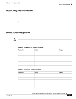
Using VTP Chapter 8 Configuring VLANs Configuring VTP You can configure VTP through the CLI by entering commands in the VLAN database command mode. When you enter the exit command in VLAN database mode, it applies all the commands that you entered. VTP messages are sent to other switches in the VTP domain, and you enter privileged EXEC mode. If you are configuring VTP on a cluster member switch to a VLAN, first log in to the member switch by using the privileged EXEC rcommand command. For more information on how to use this command, refer to the switch command reference. Note The Cisco IOS end and Ctrl-Z commands are not supported in VLAN database mode. After you configure VTP, you must configure a trunk port so that the switch can send and receive VTP advertisements. For more information, see the "How VLAN Trunks Work" section on page 8-26. Configuring VTP Server Mode When a switch is in VTP server mode, you can change the VLAN configuration and have it propagated throughout the network. Beginning in privileged EXEC mode, follow these steps to configure the switch for VTP server mode: Step 1 Step 2 Command vlan database vtp domain domain-name Step 3 vtp password password-value Step 4 Step 5 Step 6 vtp server exit show vtp status Purpose Enter VLAN database mode. Configure a VTP administrative-domain name. The name can be from 1 to 32 characters. All switches operating in VTP server or client mode under the same administrative responsibility must be configured with the same domain name. (Optional) Set a password for the VTP domain. The password can be from 8 to 64 characters. If you configure a VTP password, the VTP domain does not function properly if you do not assign the same password to each switch in the domain. Configure the switch for VTP server mode (the default). Return to privileged EXEC mode. Verify the VTP configuration. In the display, check the VTP Operating Mode and the VTP Domain Name fields. 8-16 Catalyst 2900 Series XL and Catalyst 3500 Series XL Software Configuration Guide 78-6511-08
-
 1
1 -
2
-
3
-
4
-
5
-
6
-
7
-
8
-
9
-
10
-
11
-
12
-
13
-
14
-
15
-
16
-
17
-
18
-
19
-
20
-
21
-
22
-
23
-
24
-
25
-
26
-
27
-
28
-
29
-
30
-
31
-
32
-
33
-
34
-
35
-
36
-
37
-
38
-
39
-
40
-
41
-
42
-
43
-
44
-
45
-
46
-
47
-
48
-
49
-
50
-
51
-
52
-
53
-
54
-
55
-
56
-
57
-
58
-
59
-
60
-
61
-
62
-
63
-
64
-
65
-
66
-
67
-
68
-
69
-
70
-
71
-
72
-
73
-
74
-
75
-
76
-
77
-
78
-
79
-
80
-
81
-
82
-
83
-
84
-
85
-
86
-
87
-
88
-
89
-
90
-
91
-
92
-
93
-
94
-
95
-
96
-
97
-
98
-
99
-
100
-
101
-
102
-
103
-
104
-
105
-
106
-
107
-
108
-
109
-
110
-
111
-
112
-
113
-
114
-
115
-
116
-
117
-
118
-
119
-
120
-
121
-
122
-
123
-
124
-
125
-
126
-
127
-
128
-
129
-
130
-
131
-
132
-
133
-
134
-
135
-
136
-
137
-
138
-
139
-
140
-
141
-
142
-
143
-
144
-
145
-
146
-
147
-
148
-
149
-
150
-
151
-
152
-
153
-
154
-
155
-
156
-
157
-
158
-
159
-
160
-
161
-
162
-
163
-
164
-
165
-
166
-
167
-
168
-
169
-
170
-
171
-
172
-
173
-
174
-
175
-
176
-
177
-
178
-
179
-
180
-
181
-
182
-
183
-
184
-
185
-
186
-
187
-
188
-
189
-
190
-
191
-
192
-
193
-
194
-
195
-
196
-
197
-
198
-
199
-
200
-
201
-
202
-
203
-
204
-
205
-
206
-
207
-
208
-
209
-
210
-
211
-
212
-
213
-
214
-
215
-
216
-
217
-
218
-
219
-
220
-
221
-
222
-
223
-
224
-
225
-
226
-
227
-
228
-
229
-
230
-
231
-
232
-
 233
233 -
 234
234 -
 235
235 -
 236
236 -
 237
237 -
 238
238 -
 239
239 -
 240
240 -
 241
241 -
 242
242 -
 243
243 -
244
-
245
-
246
-
247
-
248
-
249
-
250
-
251
-
252
-
253
-
254
-
255
-
256
-
257
-
258
-
259
-
260
-
261
-
262
-
263
-
264
-
265
-
266
-
267
-
268
-
269
-
270
-
271
-
272
-
273
-
274
-
275
-
276
-
277
-
278
-
279
-
280
-
281
-
282
-
283
-
284
-
285
-
286
-
287
-
288
-
289
-
290
-
291
-
292
-
293
-
294
-
295
-
296
-
297
-
298
-
299
-
300
-
301
-
302
-
303
-
304
-
305
-
306
-
307
-
308
-
309
-
310
-
311
-
312
-
313
-
314
-
315
-
316
-
317
-
318
-
319
-
320
-
321
-
322
-
323
-
324
-
325
-
326
-
327
-
328
-
329
-
330
-
331
-
332
-
333
-
334
-
335
-
336
-
337
-
338
-
339
-
340
-
341
-
342
-
343
-
344
-
345
-
346
-
347
-
348
-
349
-
350
-
351
-
352
-
353
-
354
-
355
-
356
-
357
-
358
-
359
-
360
-
361
-
362
-
363
-
364
-
365
-
366
-
367
-
368
 |
 |
