Compaq 270680-003 Compaq Reference Guide Deskpro 4000 and Deskpro 6000 Series - Page 11
Desktop Rear Panel Components, Connector, Function
 |
View all Compaq 270680-003 manuals
Add to My Manuals
Save this manual to your list of manuals |
Page 11 highlights
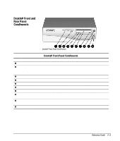
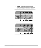
Ref. 1 2 3 4 5 6 7 8 9 : ; < = > ? @ A Desktop Rear Panel Components Connector Function Power Cord Connects the computer to an electrical power outlet. Monitor Connector Connects a monitor. NOTE: Your computer will include either a PCI or an AGP monitor connector, but not both. Ethernet AUI Connector Connects the Ethernet network, using an AUI cable or an AUI to BNC transceiver. Universal Serial Bus (USB) Connectors Connects the computer to any USB peripheral while the computer is operating; are fully functional Plug and Play connectors. Serial Connectors Connects a serial device, such as a serial mouse or scanner. Mouse Connector Connects the mouse. (Green-colored icon) Microphone Connector Connects a microphone. (CD-ROM drive models; bluecolored icon) Line-In Audio Connector Connects a device that supplies sound, such as a tape deck or CD player. (CD-ROM drive models) Line-Out Audio Connector Connects an external amplifier (to power additional speakers) or a tape deck for recording. (CD-ROM drive models) Headphone Connector Connects headphones. (CD-ROM drive models) Keyboard Connector Connects the keyboard. (Orange-colored icon) External Infrared Transceiver Connector Connects an optional external infrared transceiver. (Yellowcolored icon) Ethernet RJ-45 Connector Connects the Ethernet network, using an RJ-45 cable. Network Status Lights Yellow link light turns on when network driver is properly loaded and system is physically connected to a network. Green activity light turns on when system detects network activity. Parallel Port Connector Connects a parallel device, such as a parallel printer. Voltage Select Switch Switches voltage between 115V (U.S.) and 230V to match geographical requirements. Ultra-SCSI Connector Connects external SCSI devices. (Deskpro 6000 models) Reference Guide 1-5
-
 1
1 -
2
-
3
-
4
-
5
-
 6
6 -
 7
7 -
 8
8 -
 9
9 -
 10
10 -
 11
11 -
 12
12 -
 13
13 -
 14
14 -
 15
15 -
 16
16 -
17
-
18
-
19
-
20
-
21
-
22
-
23
-
24
-
25
-
26
-
27
-
28
-
29
-
30
-
31
-
32
-
33
-
34
-
35
-
36
-
37
-
38
-
39
-
40
-
41
-
42
-
43
-
44
-
45
-
46
-
47
-
48
-
49
-
50
-
51
-
52
-
53
-
54
-
55
-
56
-
57
-
58
-
59
-
60
-
61
-
62
-
63
-
64
-
65
-
66
-
67
-
68
-
69
-
70
-
71
-
72
-
73
-
74
-
75
-
76
-
77
-
78
-
79
-
80
-
81
-
82
-
83
-
84
-
85
-
86
-
87
-
88
-
89
-
90
-
91
-
92
-
93
-
94
-
95
-
96
-
97
-
98
-
99
-
100
-
101
-
102
-
103
-
104
-
105
-
106
-
107
-
108
-
109
-
110
-
111
-
112
-
113
-
114
-
115
-
116
-
117
-
118
-
119
-
120
-
121
-
122
-
123
-
124
-
125
-
126
-
127
-
128
-
129
-
130
-
131
-
132
-
133
-
134
-
135
-
136
-
137
-
138
-
139
-
140
-
141
-
142
-
143
-
144
-
145
-
146
-
147
-
148
-
149
-
150
-
151
-
152
-
153
-
154
-
155
-
156
-
157
-
158
-
159
-
160
-
161
-
162
-
163
-
164
-
165
-
166
-
167
-
168
-
169
-
170
-
171
-
172
-
173
-
174
-
175
-
176
-
177
-
178
-
179
-
180
-
181
-
182
-
183
-
184
-
185
-
186
-
187
-
188
-
189
-
190
-
191
-
192
-
193
-
194
-
195
-
196
-
197
-
198
-
199
-
200
-
201
-
202
-
203
-
204
-
205
-
206
-
207
-
208
-
209
-
210
-
211
-
212
-
213
-
214
-
215
-
216
-
217
-
218
-
219
-
220
-
221
-
222
-
223
-
224
-
225
-
226
-
227
-
228
-
229
-
230
-
231
-
232
-
233
-
234
 |
 |
