Compaq ML530R Service Guide - Page 41
Cable Routing Diagrams
 |
UPC - 720591250300
View all Compaq ML530R manuals
Add to My Manuals
Save this manual to your list of manuals |
Page 41 highlights
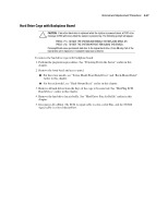
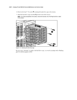
2-26 Compaq ProLiant ML530 Servers Maintenance and Service Guide Cable Routing Diagrams The location and routing of each cable in Compaq ProLiant ML530 servers is shown in the following diagrams. For further information, refer to the Compaq ProLiant ML530 Setup and Installation Guide. To improve serviceability, the signal cables and system board are color-coded as follows: Blue = SCSI A Yellow = SCSI B Orange = CD-ROM drive Purple = Diskette drive When replacing the system board or power backplane board, remove the cables in the following sequence for easier accessibility. CAUTION: Due to the sliding design of the system board tray, the cables must be routed properly. Cables can be damaged by pinching or chafing if not routed or contained properly. IMPORTANT: Some cables are held to the side of the chassis with cable clips or are bound by straps with hook-and-loop fasteners to keep the cables properly stored. The clips can be opened by releasing the clip tab. Replace the cable in the clips or strap when completing cable routing procedures. NOTE: Remove the PCI bracket for easier access. See "PCI Bracket" later in the chapter. 1. Power cables for system fans. See Figure 2-18. 2. Signal cables for SCSI hard drives and removable media devices (blue and yellow cables). See Figure 2-19 and Figure 2-20. 3. Power and signal cables for the CD-ROM and diskette drives (orange and purple cables, respectively). See Figure 2-21. 4. System data cable. See Figure 2-22. 5. System power cables. See Figure 2-23. 6. Power cables for SCSI hard drives and removable media devices. See Figure 2-24. 7. Power cables for drive fans. See Figure 2-25. Reverse steps 1 through 7 to connect power and signal cables.
-
 1
1 -
2
-
3
-
4
-
5
-
6
-
7
-
8
-
9
-
10
-
11
-
12
-
13
-
14
-
15
-
16
-
17
-
18
-
19
-
20
-
21
-
22
-
23
-
24
-
25
-
26
-
27
-
28
-
29
-
30
-
31
-
32
-
33
-
34
-
35
-
 36
36 -
 37
37 -
 38
38 -
 39
39 -
 40
40 -
 41
41 -
 42
42 -
 43
43 -
 44
44 -
 45
45 -
 46
46 -
47
-
48
-
49
-
50
-
51
-
52
-
53
-
54
-
55
-
56
-
57
-
58
-
59
-
60
-
61
-
62
-
63
-
64
-
65
-
66
-
67
-
68
-
69
-
70
-
71
-
72
-
73
-
74
-
75
-
76
-
77
-
78
-
79
-
80
-
81
-
82
-
83
-
84
-
85
-
86
-
87
-
88
-
89
-
90
-
91
-
92
-
93
-
94
-
95
-
96
-
97
-
98
-
99
-
100
-
101
-
102
-
103
-
104
-
105
-
106
-
107
-
108
-
109
-
110
-
111
-
112
-
113
-
114
-
115
-
116
-
117
-
118
-
119
-
120
-
121
-
122
-
123
-
124
-
125
-
126
-
127
-
128
-
129
-
130
-
131
-
132
-
133
-
134
-
135
-
136
-
137
-
138
-
139
-
140
-
141
-
142
-
143
-
144
-
145
-
146
-
147
-
148
-
149
-
150
-
151
-
152
-
153
-
154
-
155
-
156
-
157
-
158
-
159
-
160
-
161
-
162
-
163
-
164
-
165
-
166
-
167
-
168
 |
 |
