Compaq nx9010 Maintenance and Service Guide - Page 4

s, Removing the Heat Sink with Fan - service manual

Page 4 highlights

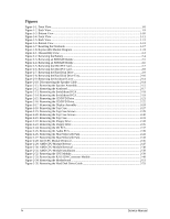
Figures Figure 1-1. Front View...1-8 Figure 1-2. Back View ...1-9 Figure 1-3. Bottom View...1-10 Figure 1-4. Front View...1-11 Figure 1-5. Back View ...1-12 Figure 1-6. Bottom View...1-13 Figure 1-7. Resetting the Notebook ...1-17 Figure 1-8. Replaceable Module Diagram 1-24 Figure 2-1. Disassembly Flow...2-3 Figure 2-2. Removing the Battery ...2-4 Figure 2-3. Removing an SDRAM Module 2-5 Figure 2-4. Removing an SDRAM Module 2-6 Figure 2-5. Removing the Mini PCI Card 2-7 Figure 2-6. Removing the Mini PCI Card 2-8 Figure 2-7. Removing the Hard Disk Drive 2-9 Figure 2-8. Removing the Hard Disk Drive Tray 2-10 Figure 2-9. Removing the Keyboard Cover 2-14 Figure 2-10. Disconnecting the Speaker Cable 2-14 Figure 2-11. Removing the Speaker Assembly 2-15 Figure 2-12. Removing the Keyboard ...2-17 Figure 2-13. Removing the Switchboard PCA 2-18 Figure 2-14. Removing the Switchboard PCA 2-19 Figure 2-15. Removing the CD/DVD Drive 2-21 Figure 2-16. Removing the CD/DVD Drive 2-22 Figure 2-17. Removing the Display Assembly 2-24 Figure 2-18. Removing the Top Case...2-27 Figure 2-19. Removing the Top Case Screws 2-29 Figure 2-20. Removing the Top Case Screws 2-30 Figure 2-21. Removing the Top Case...2-31 Figure 2-22. Removing the Floppy Drive 2-33 Figure 2-23. Removing the Floppy Drive 2-35 Figure 2-24. Removing the I/R PCA...2-37 Figure 2-25. Removing the Audio PCA ...2-39 Figure 2-26. Removing the Heat Sink (with Fan 2-41 Figure 2-27. Removing the Heat Sink (with Fan 2-43 Figure 2-28. Intel CPU Module Removal 2-45 Figure 2-29. AMD CPU Module Release 2-47 Figure 2-30. AMD CPU Module Removal 2-38 Figure 2-31. AMD CPU Module Installation 2-39 Figure 2-32 Removing the CPU Module 2-39 Figure 2-33. Removing the RJ11/1394 Connector Module 2-49 Figure 2-34. Removing the Motherboard 2-51 Figure 2-35. Removing the Hard Disk Drive Guide 2-53 iv Service Manual

  • 1
  • 2
  • 3
  • 4
  • 5
  • 6
  • 7
  • 8
  • 9
  • 10
  • 11
  • 12
  • 13
  • 14
  • 15
  • 16
  • 17
  • 18
  • 19
  • 20
  • 21
  • 22
  • 23
  • 24
  • 25
  • 26
  • 27
  • 28
  • 29
  • 30
  • 31
  • 32
  • 33
  • 34
  • 35
  • 36
  • 37
  • 38
  • 39
  • 40
  • 41
  • 42
  • 43
  • 44
  • 45
  • 46
  • 47
  • 48
  • 49
  • 50
  • 51
  • 52
  • 53
  • 54
  • 55
  • 56
  • 57
  • 58
  • 59
  • 60
  • 61
  • 62
  • 63
  • 64
  • 65
  • 66
  • 67
  • 68
  • 69
  • 70
  • 71
  • 72
  • 73
  • 74
  • 75
  • 76
  • 77
  • 78
  • 79
  • 80
  • 81
  • 82
  • 83
  • 84
  • 85
  • 86
  • 87
  • 88
  • 89
  • 90
  • 91
  • 92
  • 93
  • 94
  • 95
  • 96
  • 97
  • 98
  • 99
  • 100
  • 101
  • 102
  • 103
  • 104
  • 105
  • 106
  • 107
  • 108
  • 109
  • 110
  • 111
  • 112
  • 113
  • 114
  • 115
  • 116
  • 117
  • 118
  • 119
  • 120
  • 121
  • 122
  • 123
  • 124
  • 125
  • 126
  • 127
  • 128
  • 129
  • 130
  • 131
  • 132
  • 133
  • 134
  • 135
  • 136
  • 137
  • 138
  • 139
  • 140
  • 141
  • 142
  • 143
  • 144
  • 145
  • 146
  • 147
  • 148
  • 149
  • 150
  • 151
  • 152
  • 153
  • 154

Figures
Figure 1-1. Front View
................................................................................................................................
1-8
Figure 1-2. Back View
................................................................................................................................
1-9
Figure 1-3. Bottom View
...........................................................................................................................
1-10
Figure 1-4. Front View
..............................................................................................................................
1-11
Figure 1-5. Back View
..............................................................................................................................
1-12
Figure 1-6. Bottom View
...........................................................................................................................
1-13
Figure 1-7. Resetting the Notebook
..........................................................................................................
1-17
Figure 1-8. Replaceable Module Diagram
................................................................................................
1-24
Figure 2-1. Disassembly Flow
.....................................................................................................................
2-3
Figure 2-2. Removing the Battery
...............................................................................................................
2-4
Figure 2-3. Removing an SDRAM Module
................................................................................................
2-5
Figure 2-4. Removing an SDRAM Module
................................................................................................
2-6
Figure 2-5. Removing the Mini PCI Card
...................................................................................................
2-7
Figure 2-6. Removing the Mini PCI Card
...................................................................................................
2-8
Figure 2-7. Removing the Hard Disk Drive
................................................................................................
2-9
Figure 2-8. Removing the Hard Disk Drive Tray
......................................................................................
2-10
Figure 2-9. Removing the Keyboard Cover
..............................................................................................
2-14
Figure 2-10. Disconnecting the Speaker Cable
.........................................................................................
2-14
Figure 2-11. Removing the Speaker Assembly
.........................................................................................
2-15
Figure 2-12. Removing the Keyboard
.......................................................................................................
2-17
Figure 2-13. Removing the Switchboard PCA
..........................................................................................
2-18
Figure 2-14. Removing the Switchboard PCA
..........................................................................................
2-19
Figure 2-15. Removing the CD/DVD Drive
.............................................................................................
2-21
Figure 2-16. Removing the CD/DVD Drive
.............................................................................................
2-22
Figure 2-17. Removing the Display Assembly
.........................................................................................
2-24
Figure 2-18. Removing the Top Case
........................................................................................................
2-27
Figure 2-19. Removing the Top Case Screws
...........................................................................................
2-29
Figure 2-20. Removing the Top Case Screws
...........................................................................................
2-30
Figure 2-21. Removing the Top Case
........................................................................................................
2-31
Figure 2-22. Removing the Floppy Drive
.................................................................................................
2-33
Figure 2-23. Removing the Floppy Drive
.................................................................................................
2-35
Figure 2-24. Removing the I/R PCA
.........................................................................................................
2-37
Figure 2-25. Removing the Audio PCA
....................................................................................................
2-39
Figure 2-26. Removing the Heat Sink (with Fan)
.....................................................................................
2-41
Figure 2-27. Removing the Heat Sink (with Fan)
.....................................................................................
2-43
Figure 2-28. Intel CPU Module Removal
.................................................................................................
2-45
Figure 2-29. AMD CPU Module Release
.................................................................................................
2-47
Figure 2-30. AMD CPU Module Removal
..............................................................................................
2-38
Figure 2-31. AMD CPU Module Installation
............................................................................................
2-39
Figure 2-32
Removing the CPU Module
.................................................................................................
2-39
Figure 2-33. Removing the RJ11/1394 Connector Module
......................................................................
2-49
Figure 2-34. Removing the Motherboard
..................................................................................................
2-51
Figure 2-35. Removing the Hard Disk Drive Guide
.................................................................................
2-53
Service Manual
i
v