Compaq nx9010 Maintenance and Service Guide - Page 83
Disconnecting the Motherboard Cables
 |
View all Compaq nx9010 manuals
Add to My Manuals
Save this manual to your list of manuals |
Page 83 highlights
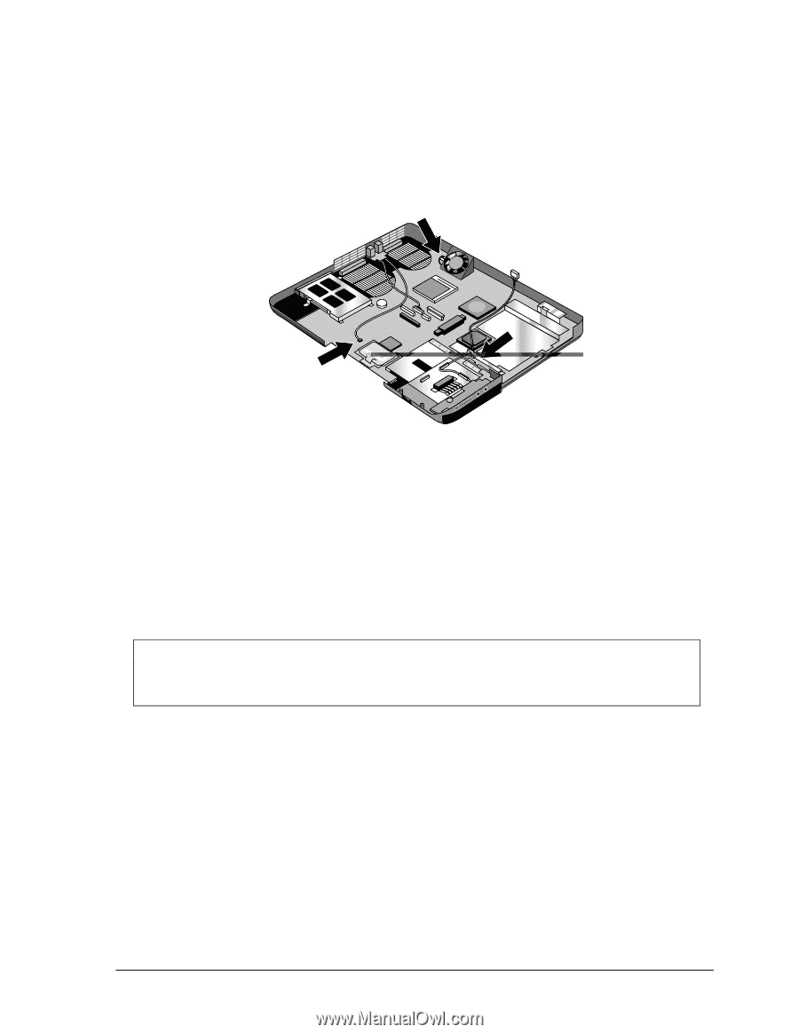
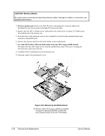
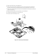
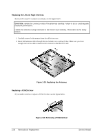
7. Disconnect the modem board cable from the motherboard. 8. Disconnect the 1394 board cable from the motherboard. 9. Disconnect the fan cable from the motherboard and remove the fan. 10. Disconnect the audio board cable from the motherboard. Figure 2-36. Disconnecting the Motherboard Cables 11. Remove the four M5.0×10mm standoffs from the notebook rear panel (2 on each side of the parallel and external monitor connectors). 12. Remove the three M2.5×6.0mm screws that secure the CD/DVD drive rear alignment rail to the bottom case. 13. Remove the CD/DVD drive rear alignment rail. 14. Remove the 2 screws that secure the CD/DVD drive front alignment rail to the bottom case. NOTE: The 2 screws that secure the CD/DVD drive front alignment rail to the bottom case are 2 different sizes. The screw that secures the left side of the rail is a M2.0×4.0mm screw. The screw that secures the right side of the rail is a M2.5×6.0mm countersink screw. Make sure these screws are installed in the correct locations when reinstalling the CD/DVD drive front alignment rail. Service Manual Removal and Replacement 2-53
-
 1
1 -
2
-
3
-
4
-
5
-
6
-
7
-
8
-
9
-
10
-
11
-
12
-
13
-
14
-
15
-
16
-
17
-
18
-
19
-
20
-
21
-
22
-
23
-
24
-
25
-
26
-
27
-
28
-
29
-
30
-
31
-
32
-
33
-
34
-
35
-
36
-
37
-
38
-
39
-
40
-
41
-
42
-
43
-
44
-
45
-
46
-
47
-
48
-
49
-
50
-
51
-
52
-
53
-
54
-
55
-
56
-
57
-
58
-
59
-
60
-
61
-
62
-
63
-
64
-
65
-
66
-
67
-
68
-
69
-
70
-
71
-
72
-
73
-
74
-
75
-
76
-
77
-
 78
78 -
 79
79 -
 80
80 -
 81
81 -
 82
82 -
 83
83 -
 84
84 -
 85
85 -
 86
86 -
 87
87 -
 88
88 -
89
-
90
-
91
-
92
-
93
-
94
-
95
-
96
-
97
-
98
-
99
-
100
-
101
-
102
-
103
-
104
-
105
-
106
-
107
-
108
-
109
-
110
-
111
-
112
-
113
-
114
-
115
-
116
-
117
-
118
-
119
-
120
-
121
-
122
-
123
-
124
-
125
-
126
-
127
-
128
-
129
-
130
-
131
-
132
-
133
-
134
-
135
-
136
-
137
-
138
-
139
-
140
-
141
-
142
-
143
-
144
-
145
-
146
-
147
-
148
-
149
-
150
-
151
-
152
-
153
-
154
 |
 |