Compaq nx9010 Maintenance and Service Guide - Page 91
Removing Other Components, Service Partners Only, Required Equipment, Removal Procedure - bios
 |
View all Compaq nx9010 manuals
Add to My Manuals
Save this manual to your list of manuals |
Page 91 highlights
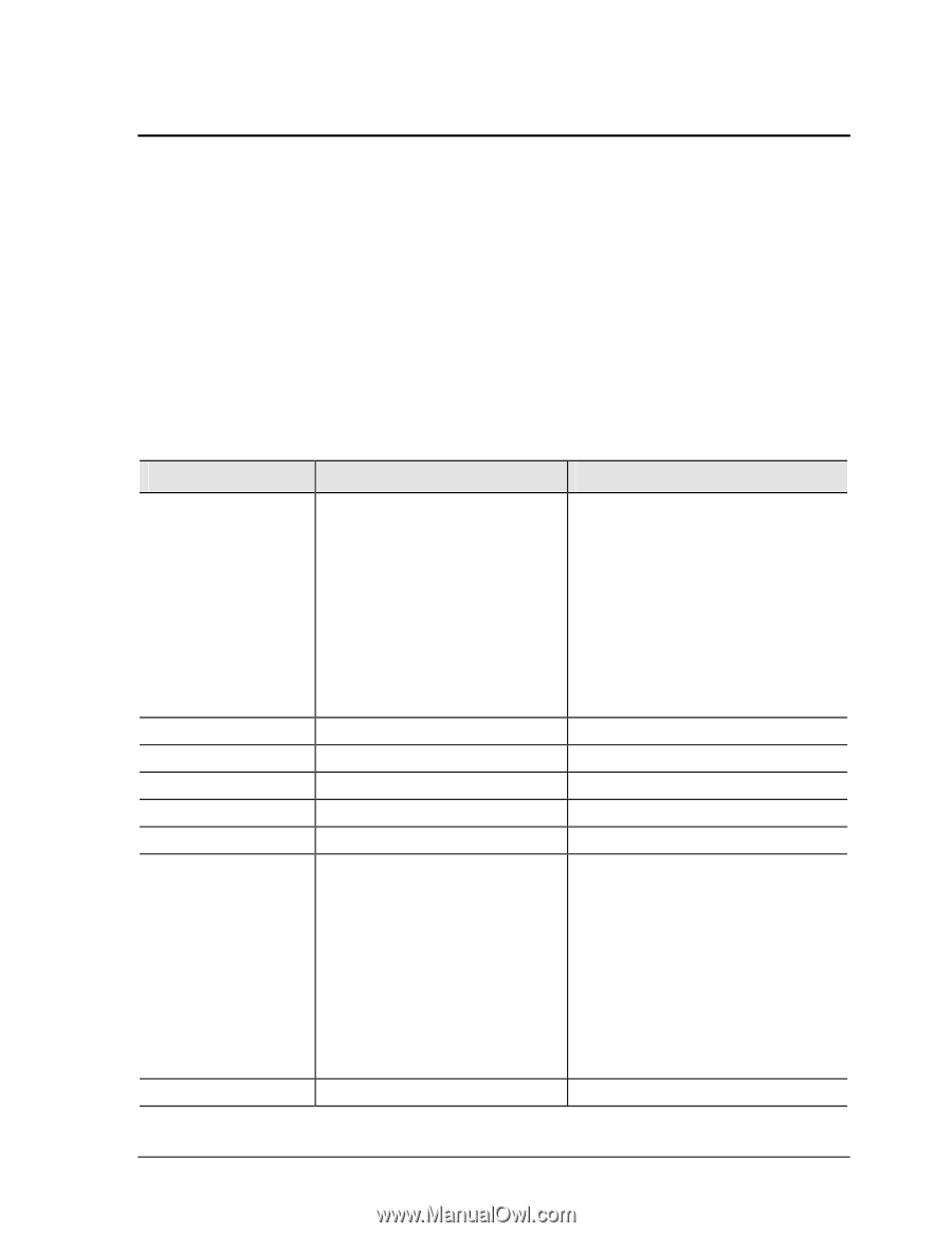
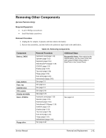
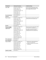
Removing Other Components (Service Partners Only) Required Equipment • 0 and 1 Phillips screwdrivers • Small flat-blade screwdriver Removal Procedure 1. Unplug the AC adapter, if present, and then remove the battery. 2. Remove the assemblies, and then follow the additional steps listed in the table below. Table 2-5. Removing Components Component Battery, CMOS Case, bottom Case, top CD/DVD drive CPU module Display assembly Doors, PCMCIA Floppy drive Removal Procedure Keyboard cover(page 2-13) Speaker (page 2-15) Keyboard (page 2-16) Switchboard PCA(page 2-19) CD/DVD (page 2-20 Display (page 2-23) Top case (page 2-26) Floppy (page 2-32) Heat sink (page 2-40) Motherboard (page 2-50) See page 2-3 See page 2-3 See page 2-3 See page 2-44 See page 2-23. Keyboard cover(page 2-13) Speaker (page 2-15) Keyboard (page 2-16) Switchboard PCA(page 2-19) CD/DVD (page 2-20 Display (page 2-23) Top case (page 2-26) Heat sink (page 2-40) Floppy (page 2-32) Motherboard (page 2-50) See page 2-32 Additional Steps Reassembly Notes: After replacing the CMOS battery, set the correct time and date using the BIOS Setup utility or Date/Time in the Control Panel. See page 2-3 Service Manual Removal and Replacement 2-61
-
 1
1 -
2
-
3
-
4
-
5
-
6
-
7
-
8
-
9
-
10
-
11
-
12
-
13
-
14
-
15
-
16
-
17
-
18
-
19
-
20
-
21
-
22
-
23
-
24
-
25
-
26
-
27
-
28
-
29
-
30
-
31
-
32
-
33
-
34
-
35
-
36
-
37
-
38
-
39
-
40
-
41
-
42
-
43
-
44
-
45
-
46
-
47
-
48
-
49
-
50
-
51
-
52
-
53
-
54
-
55
-
56
-
57
-
58
-
59
-
60
-
61
-
62
-
63
-
64
-
65
-
66
-
67
-
68
-
69
-
70
-
71
-
72
-
73
-
74
-
75
-
76
-
77
-
78
-
79
-
80
-
81
-
82
-
83
-
84
-
85
-
 86
86 -
 87
87 -
 88
88 -
 89
89 -
 90
90 -
 91
91 -
 92
92 -
 93
93 -
 94
94 -
 95
95 -
 96
96 -
97
-
98
-
99
-
100
-
101
-
102
-
103
-
104
-
105
-
106
-
107
-
108
-
109
-
110
-
111
-
112
-
113
-
114
-
115
-
116
-
117
-
118
-
119
-
120
-
121
-
122
-
123
-
124
-
125
-
126
-
127
-
128
-
129
-
130
-
131
-
132
-
133
-
134
-
135
-
136
-
137
-
138
-
139
-
140
-
141
-
142
-
143
-
144
-
145
-
146
-
147
-
148
-
149
-
150
-
151
-
152
-
153
-
154
 |
 |