Compaq nx9010 Maintenance and Service Guide - Page 92
Component, Removal Procedure, Additional Steps
 |
View all Compaq nx9010 manuals
Add to My Manuals
Save this manual to your list of manuals |
Page 92 highlights
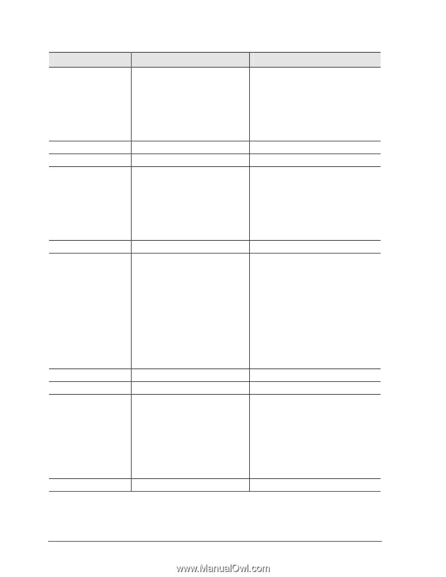
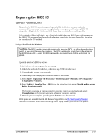
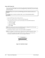
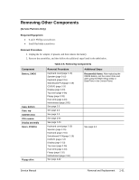
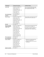
Component Guide, HDD Heat sink (with fan) Keyboard Panel, wireless PCA, I/R PCA, left and right antennas (wireless models only) PCA, motherboard PCA, switchboard Socket, PCMCIA Speaker assembly Removal Procedure Keyboard cover(page 2-13) Speaker (page 2-15) Keyboard (page 2-16) Switchboard PCA(page 2-19) CD/DVD (page 2-20 Display (page 2-23) Top case (page 2-26 See page page 2-32 See page 2-3 Keyboard cover(page 2-13) Speaker (page 2-15) Keyboard (page 2-16) Switchboard PCA(page 2-19) CD/DVD (page 2-20 Display (page 2-23) Top case (page 2-26) See page 2-36 Keyboard cover(page 2-13) Speaker (page 2-15) Keyboard (page 2-16) Switchboard PCA(page 2-19) CD/DVD (page 2-20 Display (page 2-23) Top case (page 2-26) Floppy (page 2-32) Heat sink (page 2-40) Motherboard (page 2-50) Bottom case (page 2-59) See page 2-50 See page 2-3 Keyboard cover(page 2-13) Keyboard (page 2-16) CD/DVD (page 2-20) Display (page 2-23) Top case (page 2-26) Floppy (page 2-32) Heat sink (page 2-40) Motherboard (page 2-50) See page 2-3. Additional Steps When replacing the HDD guide, make sure you only replace the 2 right screws. Do not replace the 2 left screws. Press the tabs on both sides of the panel, and then lift it from the bottom case. Disconnect the front antenna PCA cables from the Mini PCI card (page 2-7). Be careful not to bend the metal tabs on the bottom case when removing or replacing either of the 2 antenna PCAs. 1. Remove the 2 screws attaching the socket to the motherboard. 2. Unplug the PCMCIA socket from the motherboard. 2-62 Removal and Replacement Service Manual
-
 1
1 -
2
-
3
-
4
-
5
-
6
-
7
-
8
-
9
-
10
-
11
-
12
-
13
-
14
-
15
-
16
-
17
-
18
-
19
-
20
-
21
-
22
-
23
-
24
-
25
-
26
-
27
-
28
-
29
-
30
-
31
-
32
-
33
-
34
-
35
-
36
-
37
-
38
-
39
-
40
-
41
-
42
-
43
-
44
-
45
-
46
-
47
-
48
-
49
-
50
-
51
-
52
-
53
-
54
-
55
-
56
-
57
-
58
-
59
-
60
-
61
-
62
-
63
-
64
-
65
-
66
-
67
-
68
-
69
-
70
-
71
-
72
-
73
-
74
-
75
-
76
-
77
-
78
-
79
-
80
-
81
-
82
-
83
-
84
-
85
-
86
-
 87
87 -
 88
88 -
 89
89 -
 90
90 -
 91
91 -
 92
92 -
 93
93 -
 94
94 -
 95
95 -
 96
96 -
 97
97 -
98
-
99
-
100
-
101
-
102
-
103
-
104
-
105
-
106
-
107
-
108
-
109
-
110
-
111
-
112
-
113
-
114
-
115
-
116
-
117
-
118
-
119
-
120
-
121
-
122
-
123
-
124
-
125
-
126
-
127
-
128
-
129
-
130
-
131
-
132
-
133
-
134
-
135
-
136
-
137
-
138
-
139
-
140
-
141
-
142
-
143
-
144
-
145
-
146
-
147
-
148
-
149
-
150
-
151
-
152
-
153
-
154
 |
 |