Compaq nx9010 Maintenance and Service Guide - Page 84
Removing the Motherboard
 |
View all Compaq nx9010 manuals
Add to My Manuals
Save this manual to your list of manuals |
Page 84 highlights
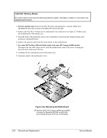
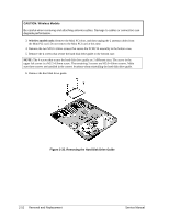
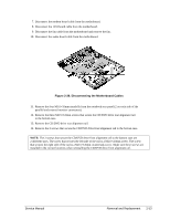
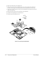
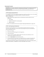
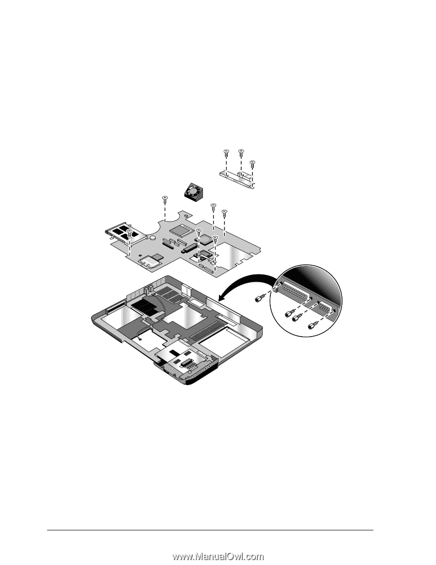
15. Remove the CD/DVD drive front alignment rail. 16. Remove the two M2.5×6.0mm countersink screws (one on the front edge of the motherboard, the other on the left edge of the motherboard) that secure the motherboard to the bottom case. 17. Remove the two M2.0×5.0mm screws that secure the motherboard to the bottom case on the back edge of the motherboard. 18. Remove the antenna cable from the metal holder on the motherboard. 19. Carefully lift the motherboard out of the bottom case. 20. If present, remove the modem port cover. Figure 2-37. Removing the Motherboard 2-54 Removal and Replacement Service Manual
-
 1
1 -
2
-
3
-
4
-
5
-
6
-
7
-
8
-
9
-
10
-
11
-
12
-
13
-
14
-
15
-
16
-
17
-
18
-
19
-
20
-
21
-
22
-
23
-
24
-
25
-
26
-
27
-
28
-
29
-
30
-
31
-
32
-
33
-
34
-
35
-
36
-
37
-
38
-
39
-
40
-
41
-
42
-
43
-
44
-
45
-
46
-
47
-
48
-
49
-
50
-
51
-
52
-
53
-
54
-
55
-
56
-
57
-
58
-
59
-
60
-
61
-
62
-
63
-
64
-
65
-
66
-
67
-
68
-
69
-
70
-
71
-
72
-
73
-
74
-
75
-
76
-
77
-
78
-
 79
79 -
 80
80 -
 81
81 -
 82
82 -
 83
83 -
 84
84 -
 85
85 -
 86
86 -
 87
87 -
 88
88 -
 89
89 -
90
-
91
-
92
-
93
-
94
-
95
-
96
-
97
-
98
-
99
-
100
-
101
-
102
-
103
-
104
-
105
-
106
-
107
-
108
-
109
-
110
-
111
-
112
-
113
-
114
-
115
-
116
-
117
-
118
-
119
-
120
-
121
-
122
-
123
-
124
-
125
-
126
-
127
-
128
-
129
-
130
-
131
-
132
-
133
-
134
-
135
-
136
-
137
-
138
-
139
-
140
-
141
-
142
-
143
-
144
-
145
-
146
-
147
-
148
-
149
-
150
-
151
-
152
-
153
-
154
 |
 |
2-54
Removal and Replacement
Service Manual
15.
Remove the CD/DVD drive front alignment rail.
16.
Remove the two M2.5×6.0mm countersink screws (one on the front edge of the motherboard,
the other on the left edge of the motherboard) that secure the motherboard to the bottom case.
17.
Remove the two M2.0×5.0mm screws that secure the motherboard to the bottom case on the back
edge of the motherboard.
18.
Remove the antenna cable from the metal holder on the motherboard.
19.
Carefully lift the motherboard out of the bottom case.
20.
If present, remove the modem port cover.
Figure 2-37. Removing the Motherboard