Dell Brocade 6520 Web Tools Administrator's Guide Supporting Fabric OS v7.1.0 - Page 59
Opening the Switch Administration window, Configuring IP and subnet mask information
 |
View all Dell Brocade 6520 manuals
Add to My Manuals
Save this manual to your list of manuals |
Page 59 highlights
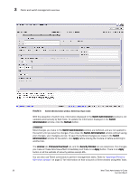
Configuring IP and subnet mask information 3 Opening the Switch Administration window Most of the management procedures in this chapter are performed from the Switch Administration window. To open the Switch Administration window, perform the following steps. 1. Click Configure > Switch Admin. The Switch Administration dialog box displays in basic mode, as shown in Figure 8 on page 30. The basic mode displays the "basic" tabs and options. 2. Click Show Advanced Mode to see all the available tabs and options. Configuring IP and subnet mask information Before proceeding, collect all the information you need to configure the Ethernet IP interface. This includes the subnet mask, gateway IP address, or IPFC, and subnet mask for your system. When you configure or change the Ethernet IP, subnet mask, gateway IP, or IPFC, and subnet mask from Web Tools, there is a normal loss of network connection to the switch. Close all current windows and restart Web Tools with the new IP address. NOTE The IPFC address is specific for each logical switch. The IPFC address is set to FC0 for switches that do not support Virtual Fabrics. To configure the IP and subnet mask information, perform the following steps. 1. Select the Network tab. 2. In the appropriate IP address section, enter the IP address you want to use for the IP interface. Use the IPv4 Address section or the IPv6 Address section to specify IP addresses. 3. In the IPv4 Address section: • In the Ethernet IP field, enter the Ethernet IP address. • In the IPFC Net IP field, enter the IPFC net IP address. • In the Ethernet Mask field, enter the Ethernet mask address. • In the IPFC Net Mask field, enter the IPFC net mask address. • In the Gateway IP field, enter the gateway IP address. 4. In the IPv6 Address section, in the Ethernet IPv6 field, enter the Ethernet IP address. 5. You can also enable automatic configuration of IPv6 addresses by selecting Enable IPv6 Auto Configuration. The automatically generated IPv6 addresses are displayed under Auto Configured IPv6 Addresses. Eight auto-configured addresses are created per switch, and up to 24 for a DCX, or DCX-4S chassis (eight per chassis, and eight per each installed CP). Web Tools Administrator's Guide 31 53-1002756-01
-
 1
1 -
2
-
3
-
4
-
5
-
6
-
7
-
8
-
9
-
10
-
11
-
12
-
13
-
14
-
15
-
16
-
17
-
18
-
19
-
20
-
21
-
22
-
23
-
24
-
25
-
26
-
27
-
28
-
29
-
30
-
31
-
32
-
33
-
34
-
35
-
36
-
37
-
38
-
39
-
40
-
41
-
42
-
43
-
44
-
45
-
46
-
47
-
48
-
49
-
50
-
51
-
52
-
53
-
 54
54 -
 55
55 -
 56
56 -
 57
57 -
 58
58 -
 59
59 -
 60
60 -
 61
61 -
 62
62 -
 63
63 -
 64
64 -
65
-
66
-
67
-
68
-
69
-
70
-
71
-
72
-
73
-
74
-
75
-
76
-
77
-
78
-
79
-
80
-
81
-
82
-
83
-
84
-
85
-
86
-
87
-
88
-
89
-
90
-
91
-
92
-
93
-
94
-
95
-
96
-
97
-
98
-
99
-
100
-
101
-
102
-
103
-
104
-
105
-
106
-
107
-
108
-
109
-
110
-
111
-
112
-
113
-
114
-
115
-
116
-
117
-
118
-
119
-
120
-
121
-
122
-
123
-
124
-
125
-
126
-
127
-
128
-
129
-
130
-
131
-
132
-
133
-
134
-
135
-
136
-
137
-
138
-
139
-
140
-
141
-
142
-
143
-
144
-
145
-
146
-
147
-
148
-
149
-
150
-
151
-
152
-
153
-
154
-
155
-
156
-
157
-
158
-
159
-
160
-
161
-
162
-
163
-
164
-
165
-
166
-
167
-
168
-
169
-
170
-
171
-
172
-
173
-
174
-
175
-
176
-
177
-
178
-
179
-
180
-
181
-
182
-
183
-
184
-
185
-
186
-
187
-
188
-
189
-
190
-
191
-
192
-
193
-
194
-
195
-
196
-
197
-
198
-
199
-
200
-
201
-
202
-
203
-
204
-
205
-
206
-
207
-
208
-
209
-
210
-
211
-
212
-
213
-
214
-
215
-
216
-
217
-
218
-
219
-
220
-
221
-
222
-
223
-
224
-
225
-
226
-
227
-
228
-
229
-
230
-
231
-
232
-
233
-
234
-
235
-
236
-
237
-
238
-
239
-
240
-
241
-
242
-
243
-
244
-
245
-
246
-
247
-
248
-
249
-
250
-
251
-
252
-
253
-
254
-
255
-
256
-
257
-
258
-
259
-
260
-
261
-
262
-
263
-
264
-
265
-
266
-
267
-
268
 |
 |