Dell External OEMR 2970 User Guide - Page 23
omreport: Viewing System Status Using the Instrumentation Service
 |
View all Dell External OEMR 2970 manuals
Add to My Manuals
Save this manual to your list of manuals |
Page 23 highlights
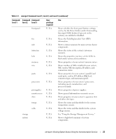
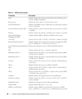
Table 3-1. omreport Command Level 1, Level 2, and Level 3 (continued) Command Command Command level 1 level 2 level 3 frontpanel User privilege required U, P, A fru info intrusion leds memory nics U, P, A U, P, A U, P, A U, P, A U, P, A U, P, A ports U, P, A processors U, P, A pwrsupplies remoteaccess slots U, P, A U, P, A U, P, A temps U, P, A volts U, P, A storage system U, P, A U, P, A Use Shows whether the front panel button settings, such as for the Power button and/or Nonmasking Interrupt (NMI) button (if present on the system), are enabled or disabled. Shows the Field Replaceable Unit (FRU) information. Shows a status summary for main system chassis components. Shows the status of the system's intrusion sensor(s). Shows the properties you have set for LEDs to flash under various alert conditions. Shows properties of your system's memory arrays. Shows number of NICs installed in your system, NIC vendor, NIC description, IP address, and connection status. Shows properties for your system's parallel and serial ports, such as I/O address, IRQ level, connector type, and maximum speed. Shows properties of your system's processors, including speed, manufacturer, and processor family. Shows properties of power supplies. Shows general information on remote access. Shows properties of your system's expansion slots and other slot types. Shows the status and thresholds for the system temperature sensors. Shows the status and thresholds for the system voltage sensors. See "Using the Storage Management Service." Shows a high-level summary of system components. omreport: Viewing System Status Using the Instrumentation Service 23
-
 1
1 -
2
-
3
-
4
-
5
-
6
-
7
-
8
-
9
-
10
-
11
-
12
-
13
-
14
-
15
-
16
-
17
-
 18
18 -
 19
19 -
 20
20 -
 21
21 -
 22
22 -
 23
23 -
 24
24 -
 25
25 -
 26
26 -
 27
27 -
 28
28 -
29
-
30
-
31
-
32
-
33
-
34
-
35
-
36
-
37
-
38
-
39
-
40
-
41
-
42
-
43
-
44
-
45
-
46
-
47
-
48
-
49
-
50
-
51
-
52
-
53
-
54
-
55
-
56
-
57
-
58
-
59
-
60
-
61
-
62
-
63
-
64
-
65
-
66
-
67
-
68
-
69
-
70
-
71
-
72
-
73
-
74
-
75
-
76
-
77
-
78
-
79
-
80
-
81
-
82
-
83
-
84
-
85
-
86
-
87
-
88
-
89
-
90
-
91
-
92
-
93
-
94
-
95
-
96
-
97
-
98
-
99
-
100
-
101
-
102
-
103
-
104
-
105
-
106
-
107
-
108
-
109
-
110
-
111
-
112
-
113
-
114
-
115
-
116
-
117
-
118
-
119
-
120
-
121
-
122
-
123
-
124
-
125
-
126
-
127
-
128
-
129
-
130
-
131
-
132
-
133
-
134
-
135
-
136
-
137
-
138
-
139
-
140
-
141
-
142
-
143
-
144
-
145
-
146
-
147
-
148
-
149
-
150
-
151
-
152
-
153
-
154
-
155
-
156
-
157
-
158
-
159
-
160
-
161
-
162
-
163
-
164
-
165
-
166
-
167
-
168
-
169
-
170
-
171
-
172
-
173
-
174
-
175
-
176
-
177
-
178
-
179
-
180
-
181
-
182
-
183
-
184
-
185
-
186
-
187
-
188
-
189
-
190
-
191
-
192
-
193
-
194
-
195
-
196
-
197
-
198
-
199
-
200
-
201
-
202
-
203
-
204
-
205
-
206
-
207
-
208
-
209
-
210
-
211
-
212
-
213
-
214
-
215
-
216
-
217
-
218
-
219
-
220
-
221
-
222
-
223
-
224
-
225
-
226
 |
 |
