Dell External OEMR 2970 User Guide - Page 72
omconfig chassis fancontrol
 |
View all Dell External OEMR 2970 manuals
Add to My Manuals
Save this manual to your list of manuals |
Page 72 highlights
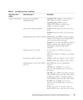
You cannot default one value and set another. In other words, if you default the minimum warning threshold value, you are also selecting the default value for the maximum warning threshold value. Specify a Value for Minimum and Maximum Warning Thresholds NOTE: Minimum and maximum warning thresholds for the fan probe cannot be set on PowerEdge x8xx and x9xx systems. If you prefer to specify values for the fan probe warning thresholds, you must specify the number of the probe you are configuring and the minimum and/or maximum warning threshold values. In the following example, the probe that is being configured is probe 0. The first command sets only the minimum threshold; the second sets minimum and maximum thresholds: omconfig chassis fans index=0 minwarnthresh=4580 omconfig chassis fans index=0 minwarnthresh=4580 maxwarnthresh=9160 When you issue the command and the system sets the values you specify, the following message appears: Fan probe warning threshold(s) set successfully. omconfig chassis fancontrol Use the omconfig chassis fancontrol command to set fan speed. You can optimize speed for cooling or for quiet operation. Table 4-7 shows the valid parameters for the command. Table 4-7. omconfig chassis fancontrol name=value pair speed=quiet speed=maxcool Description Sets fan speed for quiet operation. Sets fan speed for maximum cooling. omconfig chassis frontpanel Use the omconfig chassis frontpanel command to configure the Power button and the Nonmasking Interrupt (NMI) button and to specify and configure the LCD line number. NOTE: The Power and NMI buttons can be configured only if present on the system. Table 4-8 shows the valid parameters for the command. 72 omconfig: Managing Components Using the Instrumentation Service
-
 1
1 -
2
-
3
-
4
-
5
-
6
-
7
-
8
-
9
-
10
-
11
-
12
-
13
-
14
-
15
-
16
-
17
-
18
-
19
-
20
-
21
-
22
-
23
-
24
-
25
-
26
-
27
-
28
-
29
-
30
-
31
-
32
-
33
-
34
-
35
-
36
-
37
-
38
-
39
-
40
-
41
-
42
-
43
-
44
-
45
-
46
-
47
-
48
-
49
-
50
-
51
-
52
-
53
-
54
-
55
-
56
-
57
-
58
-
59
-
60
-
61
-
62
-
63
-
64
-
65
-
66
-
 67
67 -
 68
68 -
 69
69 -
 70
70 -
 71
71 -
 72
72 -
 73
73 -
 74
74 -
 75
75 -
 76
76 -
 77
77 -
78
-
79
-
80
-
81
-
82
-
83
-
84
-
85
-
86
-
87
-
88
-
89
-
90
-
91
-
92
-
93
-
94
-
95
-
96
-
97
-
98
-
99
-
100
-
101
-
102
-
103
-
104
-
105
-
106
-
107
-
108
-
109
-
110
-
111
-
112
-
113
-
114
-
115
-
116
-
117
-
118
-
119
-
120
-
121
-
122
-
123
-
124
-
125
-
126
-
127
-
128
-
129
-
130
-
131
-
132
-
133
-
134
-
135
-
136
-
137
-
138
-
139
-
140
-
141
-
142
-
143
-
144
-
145
-
146
-
147
-
148
-
149
-
150
-
151
-
152
-
153
-
154
-
155
-
156
-
157
-
158
-
159
-
160
-
161
-
162
-
163
-
164
-
165
-
166
-
167
-
168
-
169
-
170
-
171
-
172
-
173
-
174
-
175
-
176
-
177
-
178
-
179
-
180
-
181
-
182
-
183
-
184
-
185
-
186
-
187
-
188
-
189
-
190
-
191
-
192
-
193
-
194
-
195
-
196
-
197
-
198
-
199
-
200
-
201
-
202
-
203
-
204
-
205
-
206
-
207
-
208
-
209
-
210
-
211
-
212
-
213
-
214
-
215
-
216
-
217
-
218
-
219
-
220
-
221
-
222
-
223
-
224
-
225
-
226
 |
 |
