Dell PowerEdge C6400 EMC Installation and Service Manual - Page 23
Chassis management board specifications, Drives and storage specifications
 |
View all Dell PowerEdge C6400 manuals
Add to My Manuals
Save this manual to your list of manuals |
Page 23 highlights
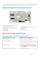
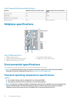
NOTE: If system with 1600 W AC PSU operates at low line 100-120 V AC, then the power rating per PSU is derated to 800 W. Chassis management board specifications Figure 18. Chassis management board specifications 1. Fan cage 1 connector for fans 1 and 2 3. Chassis management board signal cable to backplane 5. Chassis management board signal cable to PIB 7. MCU connector 9. Firmware jumpers 11. Fan cage 2 connector for fans 3 and 4 2. Left midplane signal cable 4. Chassis management board power connector from PIB 6. FPGA connector 8. COM connector 10. Right midplane signal cable Drives and storage specifications The Dell EMC PowerEdge C6400 enclosure supports SAS and SATA hard drives and Solid State Drives (SSDs). Table 8. Supported drive options for the Dell EMC PowerEdge C6400 enclosure Maximum number of drives in the enclosure Maximum number of drives assigned per sled 12 x 3.5-inch drive systems Three SAS or SATA hard drives and SSDs per sled 24 x 2.5-inch drive systems Six SAS or SATA hard drives and SSDs per sled 24 x 2.5-inch drive systems with NVMe The NVMe backplane supports either of these configurations: • Two NVMe drives and four SAS or SATA hard drives and SSDs per sled • Six SAS or SATA hard drives and SSDs per sled M.2 SATA drive (optional) The supported capacity of the M.2 SATA card is up to 240 GB NOTE: The M.2 SATA card can be installed on the x16 riser slot (slot 5). Micro-SD card (optional) for boot (up to 64 GB) One on each PCIe riser of each sled Technical specifications 23
-
 1
1 -
2
-
3
-
4
-
5
-
6
-
7
-
8
-
9
-
10
-
11
-
12
-
13
-
14
-
15
-
16
-
17
-
 18
18 -
 19
19 -
 20
20 -
 21
21 -
 22
22 -
 23
23 -
 24
24 -
 25
25 -
 26
26 -
 27
27 -
 28
28 -
29
-
30
-
31
-
32
-
33
-
34
-
35
-
36
-
37
-
38
-
39
-
40
-
41
-
42
-
43
-
44
-
45
-
46
-
47
-
48
-
49
-
50
-
51
-
52
-
53
-
54
-
55
-
56
-
57
-
58
-
59
-
60
-
61
-
62
-
63
-
64
-
65
-
66
-
67
-
68
-
69
-
70
-
71
-
72
-
73
-
74
-
75
-
76
-
77
-
78
-
79
-
80
-
81
-
82
-
83
-
84
-
85
-
86
-
87
-
88
 |
 |