Dell PowerEdge C6400 EMC Installation and Service Manual - Page 72
Backplanes and expander board, Backplane
 |
View all Dell PowerEdge C6400 manuals
Add to My Manuals
Save this manual to your list of manuals |
Page 72 highlights
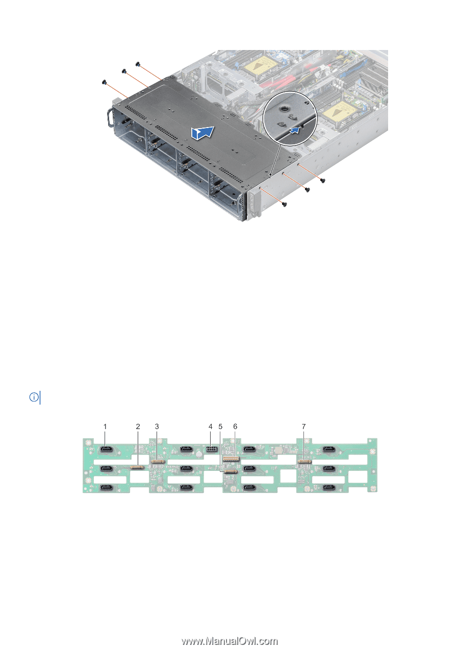
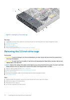
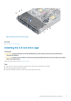
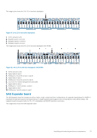
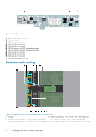
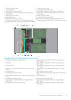
Figure 59. Installing the 3.5-inch drive cage Next steps 1. Reconnect all the backplane cables that were disconnected from the linking board and chassis management board. 2. Install all the drives. 3. Install the fan cages. 4. Follow the procedure listed in After working inside your enclosure. Backplanes and expander board Backplane The following pages contain information about the backplane and middle plane connectors. NOTE: SGPIO features will only be available on all passive backplanes at Quarter 4 2017's firmware release. The image below shows the 12 x 3.5-in hard drive backplane: Figure 60. 12 x 3.5-in hard drive backplane 1. SATA/SAS connector (12) 2. Backplane signal cable to sled 4 connector 3. Backplane signal cable to sled 3 connector 4. Backplane power connector 5. Backplane signal cable to sled 2 connector 6. Backplane signal cable connector 7. Backplane signal cable to sled 1 connector 72 Installing and removing enclosure components
-
 1
1 -
2
-
3
-
4
-
5
-
6
-
7
-
8
-
9
-
10
-
11
-
12
-
13
-
14
-
15
-
16
-
17
-
18
-
19
-
20
-
21
-
22
-
23
-
24
-
25
-
26
-
27
-
28
-
29
-
30
-
31
-
32
-
33
-
34
-
35
-
36
-
37
-
38
-
39
-
40
-
41
-
42
-
43
-
44
-
45
-
46
-
47
-
48
-
49
-
50
-
51
-
52
-
53
-
54
-
55
-
56
-
57
-
58
-
59
-
60
-
61
-
62
-
63
-
64
-
65
-
66
-
 67
67 -
 68
68 -
 69
69 -
 70
70 -
 71
71 -
 72
72 -
 73
73 -
 74
74 -
 75
75 -
 76
76 -
 77
77 -
78
-
79
-
80
-
81
-
82
-
83
-
84
-
85
-
86
-
87
-
88
 |
 |