Dell PowerEdge C6400 EMC Installation and Service Manual - Page 47
Removing a power supply unit, Policy control, Power on behavior after fault, Logging behavior
 |
View all Dell PowerEdge C6400 manuals
Add to My Manuals
Save this manual to your list of manuals |
Page 47 highlights
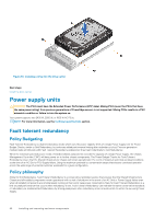
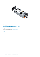
Policy control As with all Redundancy Policies, while the two Power Supplies remain healthy, load is shared evenly between them and the capacity of both Power Supplies is made available for use. In the event of an AC Grid or Power Supply failure, Power Controls will rapidly engage to restrict the power consumption of the chassis and ensure that consumption is restricted to what a single Power Supply can support. Besides the controls used with all Redundancy Policies, Fault Tolerant Redundancy also implements more performance limiting functionality which restricts the peak power after redundancy loss. For a fully loaded chassis running at maximum potential power this can result in some observed performance reduction as the chassis Power Control limits are enforced. In practice, customer workloads are often not at the maximum potential power and so practical performance reduction during an AC Grid or Power Supply failure is often minor or even unnoticeable. Power on behavior after fault In the event of an AC Grid or Power Supply failure, new chassis components are enabled to power on as long as the maximum potential power of the newly installed chassis components does not exceed the capacity of a single Power Supply when evaluated by the chassis Power Budget Checks. This means that, while customers will note a chassis "Critical" state due to the loss of redundancy, they will observe no difference in which chassis components are enabled to power on (both before and after a redundancy fault). This is because in both cases, the chassis Power Budget Checks use the capacity of only a single Power Supply. This is a key difference from the other Shared Infrastructure Chassis Redundancy Policies. Logging behavior As with all Redundancy Policies, when a Power Supply Unit fails, a log message is generated. For the Fault Tolerant Redundancy policy, a log message will also be recorded to note a "Loss of Redundancy". This message indicates that the system is continuing to operate in a Non-Redundant state, and action is necessary to either restore power to a failed AC Grid or replace a failed Power Supply Unit. Details in log messages make it possible to distinguish between these two cases. Finally, in case power-on of a chassis component is denied due to a Power Budget Check, the denial is logged both in CMC logs and iDRAC logs (in the case of compute sleds). Removing a power supply unit Prerequisites 1. Follow the safety guidelines listed in Safety instructions. 2. Disconnect the power cable from the power source and from the PSU you intend to remove, and then remove the cable from the strap on the PSU handle. Steps Press the release latch and slide the PSU out of the system by using the PSU handle. Installing and removing enclosure components 47
-
 1
1 -
2
-
3
-
4
-
5
-
6
-
7
-
8
-
9
-
10
-
11
-
12
-
13
-
14
-
15
-
16
-
17
-
18
-
19
-
20
-
21
-
22
-
23
-
24
-
25
-
26
-
27
-
28
-
29
-
30
-
31
-
32
-
33
-
34
-
35
-
36
-
37
-
38
-
39
-
40
-
41
-
 42
42 -
 43
43 -
 44
44 -
 45
45 -
 46
46 -
 47
47 -
 48
48 -
 49
49 -
 50
50 -
 51
51 -
 52
52 -
53
-
54
-
55
-
56
-
57
-
58
-
59
-
60
-
61
-
62
-
63
-
64
-
65
-
66
-
67
-
68
-
69
-
70
-
71
-
72
-
73
-
74
-
75
-
76
-
77
-
78
-
79
-
80
-
81
-
82
-
83
-
84
-
85
-
86
-
87
-
88
 |
 |