Dell PowerEdge C6400 EMC Installation and Service Manual - Page 76
Sled to hard drive mapping, Cabling the 12 x 3.5-inch backplane
 |
View all Dell PowerEdge C6400 manuals
Add to My Manuals
Save this manual to your list of manuals |
Page 76 highlights
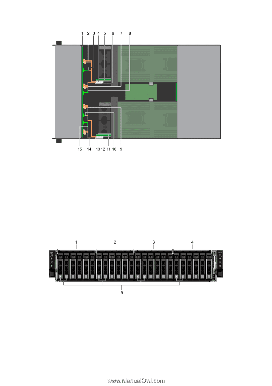
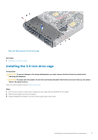
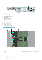
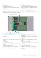
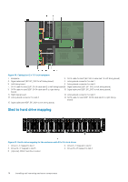
Figure 66. Cabling the 12 x 3.5-inch backplane 1. Backplane 2. SATA cable for sled 1(BP: SATA cable sled 1 to left linking board) 3. Signal cable sled 1(BP: BP_SIG1 to left linking board) 4. Linking board connector for sled 1 5. Left linking board 6. Linking board connector for sled 2 7. SATA cable for sled 2(BP: SATA cable sled 2 to left linking board)8. Signal cable sled 2(BP: BP_SIG2 to left linking board) 9. SATA cable for sled 3(BP: SATA cable sled 3 to right linking board) 10. Signal cable sled 3(BP: BP_SIG3 to left linking board) 11. Right linking board 12. Linking board connector for sled 3 13. Linking board connector for sled 4 14. SATA cable for sled 4(BP: SATA cable sled 4 to right linking board) 15. Signal cable sled 4(BP: BP_SIG4 to left linking board) Sled to hard drive mapping Figure 67. Sled to drive mapping for the enclosure with 24 x 2.5-inch drives 1. Drives 0-5 mapped to sled 1 3. Drives 12-17 mapped to sled 3 5. (Optional) NVMe hard drive location 2. Drives 6-11 mapped to sled 2 4. Drives 18-23 mapped to sled 4 76 Installing and removing enclosure components
-
 1
1 -
2
-
3
-
4
-
5
-
6
-
7
-
8
-
9
-
10
-
11
-
12
-
13
-
14
-
15
-
16
-
17
-
18
-
19
-
20
-
21
-
22
-
23
-
24
-
25
-
26
-
27
-
28
-
29
-
30
-
31
-
32
-
33
-
34
-
35
-
36
-
37
-
38
-
39
-
40
-
41
-
42
-
43
-
44
-
45
-
46
-
47
-
48
-
49
-
50
-
51
-
52
-
53
-
54
-
55
-
56
-
57
-
58
-
59
-
60
-
61
-
62
-
63
-
64
-
65
-
66
-
67
-
68
-
69
-
70
-
 71
71 -
 72
72 -
 73
73 -
 74
74 -
 75
75 -
 76
76 -
 77
77 -
 78
78 -
 79
79 -
 80
80 -
 81
81 -
82
-
83
-
84
-
85
-
86
-
87
-
88
 |
 |