Dell PowerEdge C6400 EMC Installation and Service Manual - Page 63
damaging the linking board cable connector
 |
View all Dell PowerEdge C6400 manuals
Add to My Manuals
Save this manual to your list of manuals |
Page 63 highlights
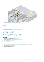
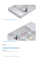
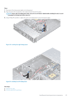
Steps 1. Reconnect all the disconnected cables to the linking board. 2. Align the board with the standoff on the chassis and slide the board into place. NOTE: Ensure that the linking board cable connector is not folded or twisted while installing the sled, to avoid damaging the linking board cable connector. 3. Using a Phillips #1 screwdriver, replace the screw on the linking board to secure the board in place. Figure 49. Installing the right linking board Figure 50. Installing the left linking board Next steps 1. Install the fan cage. 2. Install the sleds into the enclosure. Installing and removing enclosure components 63
-
 1
1 -
2
-
3
-
4
-
5
-
6
-
7
-
8
-
9
-
10
-
11
-
12
-
13
-
14
-
15
-
16
-
17
-
18
-
19
-
20
-
21
-
22
-
23
-
24
-
25
-
26
-
27
-
28
-
29
-
30
-
31
-
32
-
33
-
34
-
35
-
36
-
37
-
38
-
39
-
40
-
41
-
42
-
43
-
44
-
45
-
46
-
47
-
48
-
49
-
50
-
51
-
52
-
53
-
54
-
55
-
56
-
57
-
 58
58 -
 59
59 -
 60
60 -
 61
61 -
 62
62 -
 63
63 -
 64
64 -
 65
65 -
 66
66 -
 67
67 -
 68
68 -
69
-
70
-
71
-
72
-
73
-
74
-
75
-
76
-
77
-
78
-
79
-
80
-
81
-
82
-
83
-
84
-
85
-
86
-
87
-
88
 |
 |
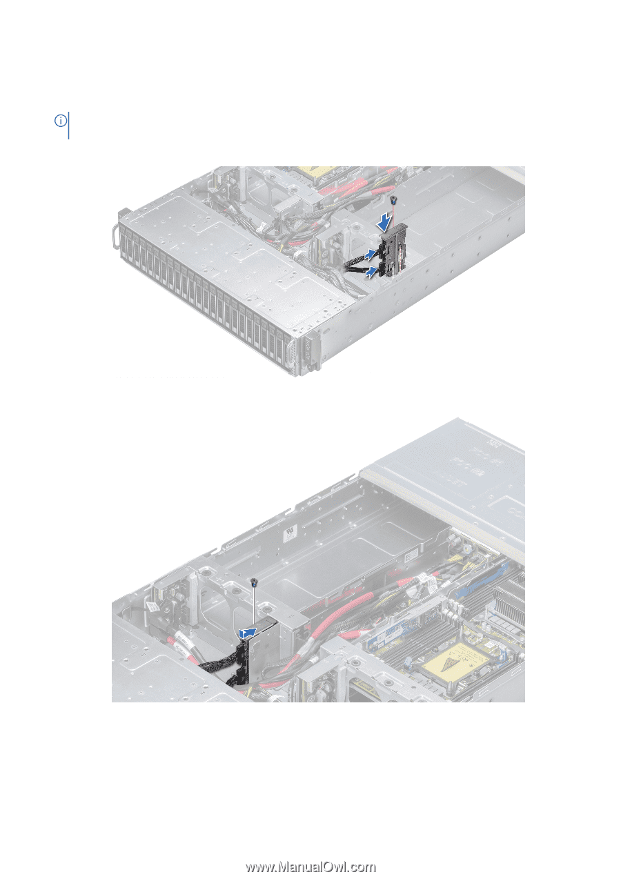
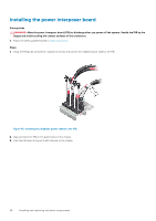
Steps
1.
Reconnect all the disconnected cables to the linking board.
2.
Align the board with the standoff on the chassis and slide the board into place.
NOTE:
Ensure that the linking board cable connector is not folded or twisted while installing the sled, to avoid
damaging the linking board cable connector.
3.
Using a Phillips #1 screwdriver, replace the screw on the linking board to secure the board in place.
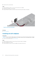
Figure 49. Installing the right linking board
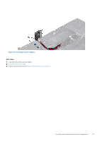
Figure 50. Installing the left linking board
Next steps
1.
Install the fan cage
.
2.
Install the sleds into the enclosure
.
Installing and removing enclosure components
63