Dell PowerEdge C6400 EMC Installation and Service Manual - Page 46
Power supply units, Fault tolerant redundancy
 |
View all Dell PowerEdge C6400 manuals
Add to My Manuals
Save this manual to your list of manuals |
Page 46 highlights
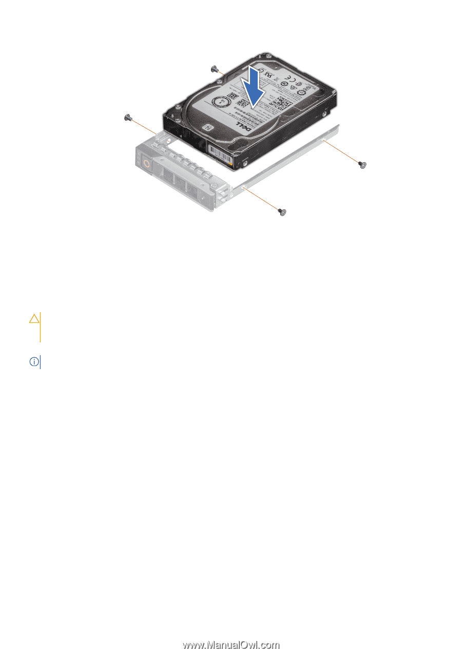
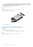
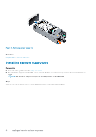
Figure 30. Installing a drive into the drive carrier Next steps Install the drive carrier. Power supply units CAUTION: The PSUs must have the Extended Power Performance (EPP) label. Mixing PSUs (even the PSUs that have the same power rating) from previous generations of PowerEdge servers is not supported. Mixing PSUs results in a PSU mismatch condition or failure to turn the system on. Your system supports two 2400 W, 2000 W, or 1600 W AC PSUs. NOTE: For more information, see the Technical specifications section. Fault tolerant redundancy Policy Budgeting Fault Tolerant Redundancy is a hybrid redundancy mode which uses the power capacity limits of a single Power Supply Unit for Power Budget Checks, similar to Grid Redundancy, but enforces added performance limiting after redundancy is lost. Previous generation modular sleds will still work with Fault Tolerant Redundancy enabled, but they treat it identically to Grid Redundancy. When the maximum potential power needs of installed chassis components exceeds the capacity of a single Power Supply, the Chassis Management Controller (CMC) will deny power on to further chassis components. The Power Budget Checks for Fault Tolerant Redundancy ensure that the Shared Infrastructure Chassis will remain operational in the event of maximum potential workload conditions at the time of an AC Grid or PSU Supply failure. Using the maximum potential is a conservative target that ensures continued operation across the wide range of potential customer workloads for a given configuration. Policy philosophy Similar to Grid Redundancy, Fault Tolerant Redundancy is a conservative redundancy policy that ensures that the Shared Infrastructure Chassis and all installed components remain operational with no risk of shutdown in the event of an AC Grid or Power Supply failure even when all installed components are simultaneously running at their worst case power consumption. New for Fault Tolerant Redundancy is a limit on peak performance that occurs when redundancy is lost. Fault Tolerant Redundancy can maintain the same conservative standards of redundancy as traditional Grid Redundancy by limiting peak power after redundancy is lost to levels which fit within the surviving Power Supply. 46 Installing and removing enclosure components
-
 1
1 -
2
-
3
-
4
-
5
-
6
-
7
-
8
-
9
-
10
-
11
-
12
-
13
-
14
-
15
-
16
-
17
-
18
-
19
-
20
-
21
-
22
-
23
-
24
-
25
-
26
-
27
-
28
-
29
-
30
-
31
-
32
-
33
-
34
-
35
-
36
-
37
-
38
-
39
-
40
-
 41
41 -
 42
42 -
 43
43 -
 44
44 -
 45
45 -
 46
46 -
 47
47 -
 48
48 -
 49
49 -
 50
50 -
 51
51 -
52
-
53
-
54
-
55
-
56
-
57
-
58
-
59
-
60
-
61
-
62
-
63
-
64
-
65
-
66
-
67
-
68
-
69
-
70
-
71
-
72
-
73
-
74
-
75
-
76
-
77
-
78
-
79
-
80
-
81
-
82
-
83
-
84
-
85
-
86
-
87
-
88
 |
 |