Dell PowerEdge C6400 EMC Installation and Service Manual - Page 70
Removing the 3.5 inch drive cage
 |
View all Dell PowerEdge C6400 manuals
Add to My Manuals
Save this manual to your list of manuals |
Page 70 highlights
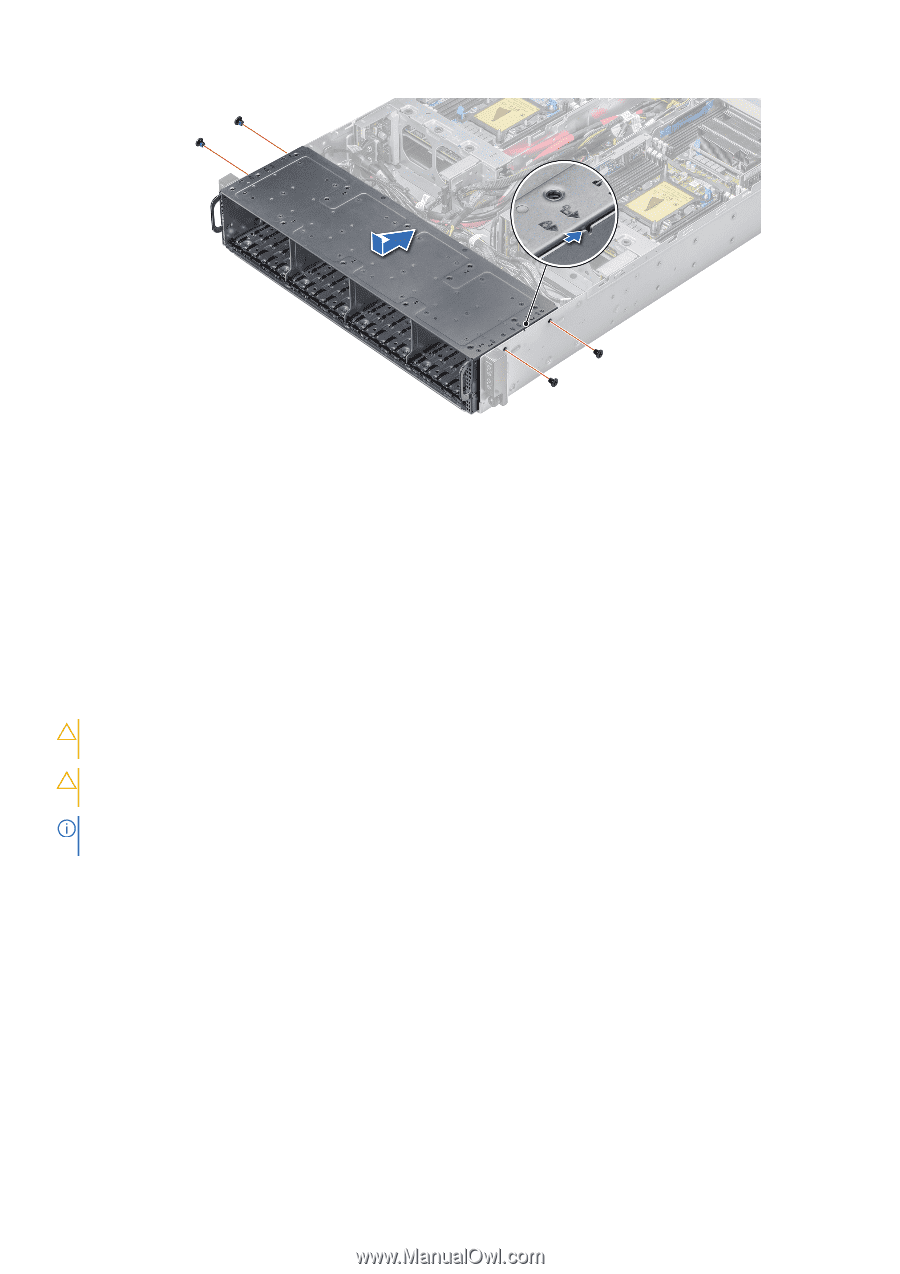
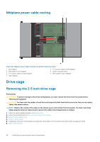
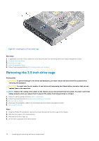
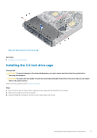
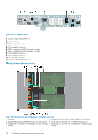
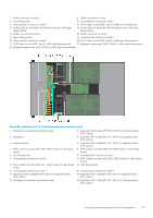
Figure 57. Installing the 2.5-inch drive cage Next steps 1. If applicable, reconnect all the cables that were disconnected from the linking board and chassis management board. 2. Install the removed drives. 3. Install the fan cage. 4. Install the backplane cover. 5. Follow the procedure listed in After working inside your enclosure. Removing the 3.5 inch drive cage Prerequisites CAUTION: To prevent damage to the drives and backplane, you must remove the drives from the system before removing the backplane. CAUTION: You must note the slot number of each drive and temporarily label them before removal so that you can replace them in the same slots. NOTE: Observe the routing of the cables on the chassis as you remove them from the system. You must route these cables properly when you replace them to prevent the cables from being pinched or crimped. 1. Follow the safety guidelines listed in Safety instructions. 2. Follow the procedure listed in Before working inside your enclosure. 3. Remove the fan cages. 4. Disconnect the backplane cables from the linking board and chassis management board. 5. Remove all the drives. Steps 1. Using the Phillips #1 screwdriver, remove the screws that secure the drive cage to the chassis. 2. Slide the drive cage to the unlock position. 3. Hold and lift the drive cage up. 4. Lift the drive cage away from the enclosure. 70 Installing and removing enclosure components
-
 1
1 -
2
-
3
-
4
-
5
-
6
-
7
-
8
-
9
-
10
-
11
-
12
-
13
-
14
-
15
-
16
-
17
-
18
-
19
-
20
-
21
-
22
-
23
-
24
-
25
-
26
-
27
-
28
-
29
-
30
-
31
-
32
-
33
-
34
-
35
-
36
-
37
-
38
-
39
-
40
-
41
-
42
-
43
-
44
-
45
-
46
-
47
-
48
-
49
-
50
-
51
-
52
-
53
-
54
-
55
-
56
-
57
-
58
-
59
-
60
-
61
-
62
-
63
-
64
-
 65
65 -
 66
66 -
 67
67 -
 68
68 -
 69
69 -
 70
70 -
 71
71 -
 72
72 -
 73
73 -
 74
74 -
 75
75 -
76
-
77
-
78
-
79
-
80
-
81
-
82
-
83
-
84
-
85
-
86
-
87
-
88
 |
 |