Dell PowerEdge C6400 EMC Installation and Service Manual - Page 8
Front view of the Dell EMC PowerEdge C6400 enclosure, Front view of the control panels
 |
View all Dell PowerEdge C6400 manuals
Add to My Manuals
Save this manual to your list of manuals |
Page 8 highlights
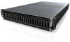
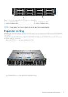
Front view of the Dell EMC PowerEdge C6400 enclosure Figure 2. Front view of the enclosure with 24 x 2.5-inch drives 1. Left control panel 3. Right control panel 2. Drive bay 4. EST tag Figure 3. Front view of the enclosure with 12 x 3.5-inch drives 1. Left control panel 3. Right control panel 2. Drive bay 4. EST tag Front view of the control panels Figure 4. Front view of the left and right control panels 8 Dell EMC PowerEdge C6400 overview
-
 1
1 -
2
-
 3
3 -
 4
4 -
 5
5 -
 6
6 -
 7
7 -
 8
8 -
 9
9 -
 10
10 -
 11
11 -
 12
12 -
 13
13 -
14
-
15
-
16
-
17
-
18
-
19
-
20
-
21
-
22
-
23
-
24
-
25
-
26
-
27
-
28
-
29
-
30
-
31
-
32
-
33
-
34
-
35
-
36
-
37
-
38
-
39
-
40
-
41
-
42
-
43
-
44
-
45
-
46
-
47
-
48
-
49
-
50
-
51
-
52
-
53
-
54
-
55
-
56
-
57
-
58
-
59
-
60
-
61
-
62
-
63
-
64
-
65
-
66
-
67
-
68
-
69
-
70
-
71
-
72
-
73
-
74
-
75
-
76
-
77
-
78
-
79
-
80
-
81
-
82
-
83
-
84
-
85
-
86
-
87
-
88
 |
 |
Front view of the Dell EMC PowerEdge C6400
enclosure
Figure 2. Front view of the enclosure with 24 x 2.5-inch drives
1.
Left control panel
2.
Drive bay
3.
Right control panel
4.
EST tag
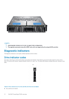
Figure 3. Front view of the enclosure with 12 x 3.5-inch drives
1.
Left control panel
2.
Drive bay
3.
Right control panel
4.
EST tag
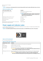
Front view of the control panels
Figure 4. Front view of the left and right control panels
8
Dell EMC PowerEdge C6400 overview