Dell PowerEdge MX840c EMC PowerEdge MX840c Installation and Service Manual - Page 118
System board, Removing the system board
 |
View all Dell PowerEdge MX840c manuals
Add to My Manuals
Save this manual to your list of manuals |
Page 118 highlights
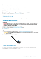
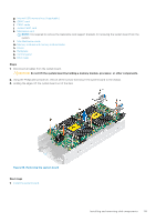
Figure 87. Installing the system battery Next steps 1. Install the PEM. 2. Follow the procedure listed in the After working inside your sled section. 3. While booting, press F2 to enter the System Setup and ensure that the battery is operating properly. 4. Enter the correct time and date in the System Setup Time and Date fields. 5. Exit the System Setup. System board A system board (also known as the motherboard) is the main printed circuit board in the system with different connectors used to connect different components or peripherals of the system. A system board provides the electrical connections to the components in the system to communicate. Removing the system board Prerequisites CAUTION: If you are using the Trusted Platform Module (TPM) with an encryption key, you may be prompted to create a recovery key during program or System Setup. Be sure to create and safely store this recovery key. If you replace this system board, you must supply the recovery key when you restart your sled or program before you can access the encrypted data on your drives. CAUTION: If either the system board or iDRAC card fails, it is required to replace the system board and iDRAC card simultaneously. NOTE: It is required to reactivate the licenses after the system board replacement. CAUTION: You may find the CMOS battery loss or CMOS checksum error displayed during the first instance of powering on the system after the processor or system board replacement which is expected. To fix this, simply go to setup option to configure the system settings. CAUTION: Do not attempt to remove the TPM plug-in module from the system board. Once the TPM plug-in module is installed, it is cryptographically bound to that specific system board. Any attempt to remove an installed TPM plug-in module breaks the cryptographic binding, and it cannot be re-installed or installed on another system board. 1. Follow the safety guidelines listed in the Safety instructions section. 2. Follow the procedure listed in the Before working inside your sled section. 3. Remove the following: a. Air shroud from the PEM b. PEM c. Air shroud from the system board d. Heat sink and processor module e. Processor blanks, if installed. CAUTION: To prevent damage to the processor socket when replacing a faulty system board, ensure that you cover the processor socket with the processor dust cover. f. IDSDM module or M.2 BOSS module 118 Installing and removing sled components
-
 1
1 -
2
-
3
-
4
-
5
-
6
-
7
-
8
-
9
-
10
-
11
-
12
-
13
-
14
-
15
-
16
-
17
-
18
-
19
-
20
-
21
-
22
-
23
-
24
-
25
-
26
-
27
-
28
-
29
-
30
-
31
-
32
-
33
-
34
-
35
-
36
-
37
-
38
-
39
-
40
-
41
-
42
-
43
-
44
-
45
-
46
-
47
-
48
-
49
-
50
-
51
-
52
-
53
-
54
-
55
-
56
-
57
-
58
-
59
-
60
-
61
-
62
-
63
-
64
-
65
-
66
-
67
-
68
-
69
-
70
-
71
-
72
-
73
-
74
-
75
-
76
-
77
-
78
-
79
-
80
-
81
-
82
-
83
-
84
-
85
-
86
-
87
-
88
-
89
-
90
-
91
-
92
-
93
-
94
-
95
-
96
-
97
-
98
-
99
-
100
-
101
-
102
-
103
-
104
-
105
-
106
-
107
-
108
-
109
-
110
-
111
-
112
-
 113
113 -
 114
114 -
 115
115 -
 116
116 -
 117
117 -
 118
118 -
 119
119 -
 120
120 -
 121
121 -
 122
122 -
 123
123 -
124
-
125
-
126
-
127
-
128
-
129
-
130
-
131
-
132
-
133
-
134
-
135
-
136
-
137
-
138
-
139
-
140
-
141
-
142
-
143
 |
 |
