Dell PowerEdge R200 Hardware Owner's Manual (PDF) - Page 16
Diagnostics Indicator Codes - diagnostic lights
 |
View all Dell PowerEdge R200 manuals
Add to My Manuals
Save this manual to your list of manuals |
Page 16 highlights
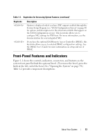
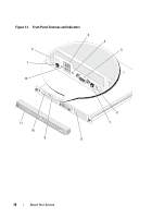
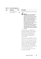
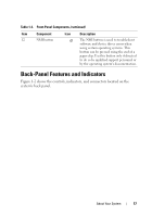
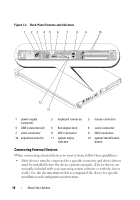
Table 1-2. Front-Panel Components (continued) Item Component Icon Description 2 Diagnostic indicators (4) The diagnostic indicators aid in diagnosing and troubleshooting the system. For more information, see "Diagnostics Indicator Codes" on page 29. 3 USB connectors (2) Connect USB 2.0-compliant devices to the system. 4 Hard-drive activity indicator 5 Video connector The green hard-drive activity indicator flashes when the hard drives are in use. Connects a monitor to the system. 6 System status indicator The blue system status indicator lights up during normal system operation. The amber system status indicator flashes when the system needs attention due to a system problem. 7 System identification button You can use the system identification buttons on the front and back panels to locate a particular system within a rack. When one of these buttons is pushed, the blue system status indicators on the front and back panels blink until one of the buttons is pushed again. You can also use the systems management software to cause the indicators to flash to identify a particular system. 8 Hard drive 1 9 Hard drive 0 10 Optical drive 11 Bezel Optional 3.5-inch SAS or SATA hard drive. A 3.5-inch SAS or SATA hard drive. Optional. Optional 16 About Your System
-
 1
1 -
2
-
3
-
4
-
5
-
6
-
7
-
8
-
9
-
10
-
 11
11 -
 12
12 -
 13
13 -
 14
14 -
 15
15 -
 16
16 -
 17
17 -
 18
18 -
 19
19 -
 20
20 -
 21
21 -
22
-
23
-
24
-
25
-
26
-
27
-
28
-
29
-
30
-
31
-
32
-
33
-
34
-
35
-
36
-
37
-
38
-
39
-
40
-
41
-
42
-
43
-
44
-
45
-
46
-
47
-
48
-
49
-
50
-
51
-
52
-
53
-
54
-
55
-
56
-
57
-
58
-
59
-
60
-
61
-
62
-
63
-
64
-
65
-
66
-
67
-
68
-
69
-
70
-
71
-
72
-
73
-
74
-
75
-
76
-
77
-
78
-
79
-
80
-
81
-
82
-
83
-
84
-
85
-
86
-
87
-
88
-
89
-
90
-
91
-
92
-
93
-
94
-
95
-
96
-
97
-
98
-
99
-
100
-
101
-
102
-
103
-
104
-
105
-
106
-
107
-
108
-
109
-
110
-
111
-
112
-
113
-
114
-
115
-
116
-
117
-
118
-
119
-
120
-
121
-
122
-
123
-
124
-
125
-
126
-
127
-
128
-
129
-
130
-
131
-
132
-
133
-
134
-
135
-
136
-
137
-
138
-
139
-
140
-
141
-
142
-
143
-
144
-
145
-
146
-
147
-
148
-
149
-
150
-
151
-
152
-
153
-
154
-
155
-
156
-
157
-
158
-
159
-
160
-
161
-
162
-
163
-
164
-
165
-
166
-
167
-
168
-
169
-
170
-
171
-
172
-
173
-
174
-
175
-
176
-
177
-
178
-
179
-
180
-
181
-
182
 |
 |