Dell PowerEdge R200 Hardware Owner's Manual (PDF) - Page 76
Replace the expansion-card retainer. See riser card until the card is fully seated.
 |
View all Dell PowerEdge R200 manuals
Add to My Manuals
Save this manual to your list of manuals |
Page 76 highlights
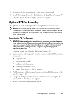
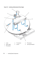
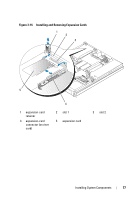
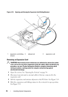
4 Remove the filler bracket on the slot you will be using. NOTE: Keep this bracket if you need to remove the expansion card. Filler brackets must be installed over empty expansion card slots to maintain Federal Communications Commission (FCC) certification of the system. The brackets also keep dust and dirt out of the system and aid in proper cooling and airflow inside the system. 5 Insert the expansion card firmly into the expansion-card connector on the riser card until the card is fully seated. NOTE: Ensure that the expansion-card bracket is also inserted into the securing slot on the chassis's back panel. 6 Replace the expansion-card retainer. See Figure 3-14. 7 Slide the expansion-card sliding retainer to the closed position so that it engages the edge of the expansion card. See Figure 3-15. 8 Connect any internal or external cable(s) to the expansion card. NOTE: You may need to remove the riser card in order to install certain expansion cards with internal connectors. See "Riser Card" on page 79. 9 Close the system. See "Closing the System" on page 55. 76 Installing System Components
-
 1
1 -
2
-
3
-
4
-
5
-
6
-
7
-
8
-
9
-
10
-
11
-
12
-
13
-
14
-
15
-
16
-
17
-
18
-
19
-
20
-
21
-
22
-
23
-
24
-
25
-
26
-
27
-
28
-
29
-
30
-
31
-
32
-
33
-
34
-
35
-
36
-
37
-
38
-
39
-
40
-
41
-
42
-
43
-
44
-
45
-
46
-
47
-
48
-
49
-
50
-
51
-
52
-
53
-
54
-
55
-
56
-
57
-
58
-
59
-
60
-
61
-
62
-
63
-
64
-
65
-
66
-
67
-
68
-
69
-
70
-
 71
71 -
 72
72 -
 73
73 -
 74
74 -
 75
75 -
 76
76 -
 77
77 -
 78
78 -
 79
79 -
 80
80 -
 81
81 -
82
-
83
-
84
-
85
-
86
-
87
-
88
-
89
-
90
-
91
-
92
-
93
-
94
-
95
-
96
-
97
-
98
-
99
-
100
-
101
-
102
-
103
-
104
-
105
-
106
-
107
-
108
-
109
-
110
-
111
-
112
-
113
-
114
-
115
-
116
-
117
-
118
-
119
-
120
-
121
-
122
-
123
-
124
-
125
-
126
-
127
-
128
-
129
-
130
-
131
-
132
-
133
-
134
-
135
-
136
-
137
-
138
-
139
-
140
-
141
-
142
-
143
-
144
-
145
-
146
-
147
-
148
-
149
-
150
-
151
-
152
-
153
-
154
-
155
-
156
-
157
-
158
-
159
-
160
-
161
-
162
-
163
-
164
-
165
-
166
-
167
-
168
-
169
-
170
-
171
-
172
-
173
-
174
-
175
-
176
-
177
-
178
-
179
-
180
-
181
-
182
 |
 |