Dell PowerEdge R200 Hardware Owner's Manual (PDF) - Page 87
Ensure that the processor socket release lever is in the fully open position. - lights
 |
View all Dell PowerEdge R200 manuals
Add to My Manuals
Save this manual to your list of manuals |
Page 87 highlights
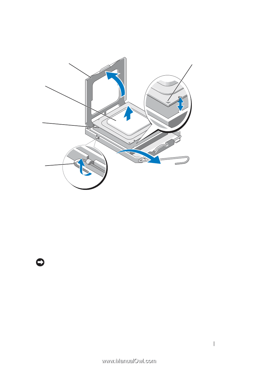
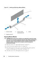
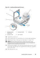
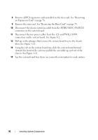
Figure 3-19. Installing and Removing the Processor 4 5 3 2 1 1 processor socket release lever 4 processor cover 2 processor socket 5 pin-1 locators 3 processor 10 Unpack the new processor. 11 Ensure that the processor socket release lever is in the fully open position. 12 Align the pin 1 corners of the processor and socket. See Figure 3-19. NOTICE: You must position the processor correctly in the socket to avoid damaging the processor and the system board when you turn on the system. Be careful not to touch or bend the pins on the socket. 13 Set the processor lightly in the socket and ensure that the processor is level in the socket. When the processor is positioned correctly, press it gently to seat it in the socket. 14 Close the processor cover. Installing System Components 87
-
 1
1 -
2
-
3
-
4
-
5
-
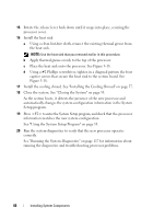
6
-
7
-
8
-
9
-
10
-
11
-
12
-
13
-
14
-
15
-
16
-
17
-
18
-
19
-
20
-
21
-
22
-
23
-
24
-
25
-
26
-
27
-
28
-
29
-
30
-
31
-
32
-
33
-
34
-
35
-
36
-
37
-
38
-
39
-
40
-
41
-
42
-
43
-
44
-
45
-
46
-
47
-
48
-
49
-
50
-
51
-
52
-
53
-
54
-
55
-
56
-
57
-
58
-
59
-
60
-
61
-
62
-
63
-
64
-
65
-
66
-
67
-
68
-
69
-
70
-
71
-
72
-
73
-
74
-
75
-
76
-
77
-
78
-
79
-
80
-
81
-
 82
82 -
 83
83 -
 84
84 -
 85
85 -
 86
86 -
 87
87 -
 88
88 -
 89
89 -
 90
90 -
 91
91 -
 92
92 -
93
-
94
-
95
-
96
-
97
-
98
-
99
-
100
-
101
-
102
-
103
-
104
-
105
-
106
-
107
-
108
-
109
-
110
-
111
-
112
-
113
-
114
-
115
-
116
-
117
-
118
-
119
-
120
-
121
-
122
-
123
-
124
-
125
-
126
-
127
-
128
-
129
-
130
-
131
-
132
-
133
-
134
-
135
-
136
-
137
-
138
-
139
-
140
-
141
-
142
-
143
-
144
-
145
-
146
-
147
-
148
-
149
-
150
-
151
-
152
-
153
-
154
-
155
-
156
-
157
-
158
-
159
-
160
-
161
-
162
-
163
-
164
-
165
-
166
-
167
-
168
-
169
-
170
-
171
-
172
-
173
-
174
-
175
-
176
-
177
-
178
-
179
-
180
-
181
-
182
 |
 |