Dell PowerEdge R200 Hardware Owner's Manual (PDF) - Page 92
floor. See Pull up on the plunger that secures the system board tray to the chassis
 |
View all Dell PowerEdge R200 manuals
Add to My Manuals
Save this manual to your list of manuals |
Page 92 highlights
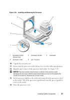
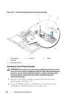
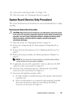
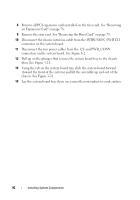
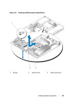
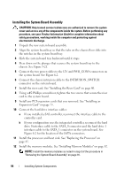
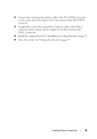
8 Remove all PCI expansion cards installed on the riser card. See "Removing an Expansion Card" on page 78. 9 Remove the riser card. See "Removing the Riser Card" on page 79. 10 Disconnect the chassis intrusion cable from the INTRUSION_SWITCH connector on the system board. 11 Disconnect the two power cables from the 12V and PWR_CONN connectors on the system board. See Figure 6-2. 12 Pull up on the plunger that secures the system board tray to the chassis floor. See Figure 3-21. 13 Using the tab on the system board tray, slide the system board forward (toward the front of the system) and lift the assembly up and out of the chassis. See Figure 3-21. 14 Lay the system board tray down on a smooth, nonconductive work surface. 92 Installing System Components
-
 1
1 -
2
-
3
-
4
-
5
-
6
-
7
-
8
-
9
-
10
-
11
-
12
-
13
-
14
-
15
-
16
-
17
-
18
-
19
-
20
-
21
-
22
-
23
-
24
-
25
-
26
-
27
-
28
-
29
-
30
-
31
-
32
-
33
-
34
-
35
-
36
-
37
-
38
-
39
-
40
-
41
-
42
-
43
-
44
-
45
-
46
-
47
-
48
-
49
-
50
-
51
-
52
-
53
-
54
-
55
-
56
-
57
-
58
-
59
-
60
-
61
-
62
-
63
-
64
-
65
-
66
-
67
-
68
-
69
-
70
-
71
-
72
-
73
-
74
-
75
-
76
-
77
-
78
-
79
-
80
-
81
-
82
-
83
-
84
-
85
-
86
-
 87
87 -
 88
88 -
 89
89 -
 90
90 -
 91
91 -
 92
92 -
 93
93 -
 94
94 -
 95
95 -
 96
96 -
 97
97 -
98
-
99
-
100
-
101
-
102
-
103
-
104
-
105
-
106
-
107
-
108
-
109
-
110
-
111
-
112
-
113
-
114
-
115
-
116
-
117
-
118
-
119
-
120
-
121
-
122
-
123
-
124
-
125
-
126
-
127
-
128
-
129
-
130
-
131
-
132
-
133
-
134
-
135
-
136
-
137
-
138
-
139
-
140
-
141
-
142
-
143
-
144
-
145
-
146
-
147
-
148
-
149
-
150
-
151
-
152
-
153
-
154
-
155
-
156
-
157
-
158
-
159
-
160
-
161
-
162
-
163
-
164
-
165
-
166
-
167
-
168
-
169
-
170
-
171
-
172
-
173
-
174
-
175
-
176
-
177
-
178
-
179
-
180
-
181
-
182
 |
 |