Dell PowerEdge R200 Hardware Owner's Manual (PDF) - Page 73
Power Supply, Removing the Power Supply
 |
View all Dell PowerEdge R200 manuals
Add to My Manuals
Save this manual to your list of manuals |
Page 73 highlights
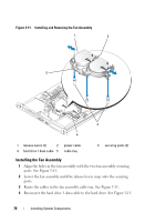
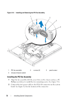
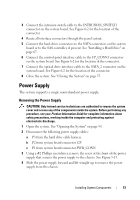
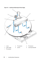
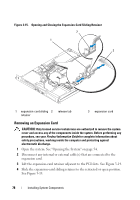
3 Connect the intrusion switch cable to the INTRUSION_SWITCH connector on the system board. See Figure 6-2 for the location of the connector. 4 Route all interface connectors through the panel cutout. 5 Connect the hard-drive connectors to the SATA connectors on the system board or to the SAS controller, if present. See "Installing a Hard Drive" on page 67. 6 Connect the control panel interface cable to the FP_CONN1 connector on the system board. See Figure 6-2 for the location of the connector. 7 Connect the optical drive interface cable to the SATA_2 connector on the system board. See Figure 6-2 for the location of the connector. 8 Close the system. See "Closing the System" on page 55. Power Supply The system supports a single nonredundant power supply. Removing the Power Supply CAUTION: Only trained service technicians are authorized to remove the system cover and access any of the components inside the system. Before performing any procedure, see your Product Information Guide for complete information about safety precautions, working inside the computer and protecting against electrostatic discharge. 1 Open the system. See "Opening the System" on page 54. 2 Disconnect the following power supply cables: a P3 from the hard drive cable harness b P2 from system board connector 12V c P1 from system board connector PWR_CONN 3 Using a #2 Phillips screwdriver, remove the screw at the front of the power supply that secures the power supply to the chassis. See Figure 3-13. 4 Slide the power supply forward and lift straight up to remove the power supply from the chassis. Installing System Components 73
-
 1
1 -
2
-
3
-
4
-
5
-
6
-
7
-
8
-
9
-
10
-
11
-
12
-
13
-
14
-
15
-
16
-
17
-
18
-
19
-
20
-
21
-
22
-
23
-
24
-
25
-
26
-
27
-
28
-
29
-
30
-
31
-
32
-
33
-
34
-
35
-
36
-
37
-
38
-
39
-
40
-
41
-
42
-
43
-
44
-
45
-
46
-
47
-
48
-
49
-
50
-
51
-
52
-
53
-
54
-
55
-
56
-
57
-
58
-
59
-
60
-
61
-
62
-
63
-
64
-
65
-
66
-
67
-
 68
68 -
 69
69 -
 70
70 -
 71
71 -
 72
72 -
 73
73 -
 74
74 -
 75
75 -
 76
76 -
 77
77 -
 78
78 -
79
-
80
-
81
-
82
-
83
-
84
-
85
-
86
-
87
-
88
-
89
-
90
-
91
-
92
-
93
-
94
-
95
-
96
-
97
-
98
-
99
-
100
-
101
-
102
-
103
-
104
-
105
-
106
-
107
-
108
-
109
-
110
-
111
-
112
-
113
-
114
-
115
-
116
-
117
-
118
-
119
-
120
-
121
-
122
-
123
-
124
-
125
-
126
-
127
-
128
-
129
-
130
-
131
-
132
-
133
-
134
-
135
-
136
-
137
-
138
-
139
-
140
-
141
-
142
-
143
-
144
-
145
-
146
-
147
-
148
-
149
-
150
-
151
-
152
-
153
-
154
-
155
-
156
-
157
-
158
-
159
-
160
-
161
-
162
-
163
-
164
-
165
-
166
-
167
-
168
-
169
-
170
-
171
-
172
-
173
-
174
-
175
-
176
-
177
-
178
-
179
-
180
-
181
-
182
 |
 |