Dell PowerEdge R200 Hardware Owner's Manual (PDF) - Page 52
components. The processor and memory are installed directly on the system - risers
 |
View all Dell PowerEdge R200 manuals
Add to My Manuals
Save this manual to your list of manuals |
Page 52 highlights
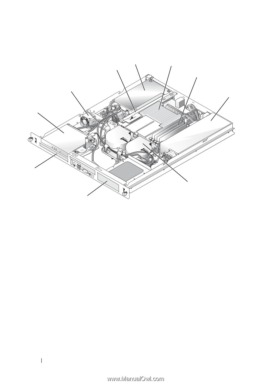
Figure 3-1. Inside the System 4 3 2 1 5 6 7 10 8 9 1 optical drive (optional) 2 4 PCI expansion card 5 (optional) 7 power supply 8 10 hard drive 0 PCI fan (optional) 3 processor and heat 6 sink processor fan module 9 riser card memory modules (4) hard drive 1 The system board holds the system's control circuitry and other electronic components. The processor and memory are installed directly on the system board. Using a riser card, the system can accommodate two expansion cards. The peripheral bays provide space for up to two hard drives and an optional optical drive. Power is supplied to the system board and drives through one nonredundant power supply. 52 Installing System Components
-
 1
1 -
2
-
3
-
4
-
5
-
6
-
7
-
8
-
9
-
10
-
11
-
12
-
13
-
14
-
15
-
16
-
17
-
18
-
19
-
20
-
21
-
22
-
23
-
24
-
25
-
26
-
27
-
28
-
29
-
30
-
31
-
32
-
33
-
34
-
35
-
36
-
37
-
38
-
39
-
40
-
41
-
42
-
43
-
44
-
45
-
46
-
 47
47 -
 48
48 -
 49
49 -
 50
50 -
 51
51 -
 52
52 -
 53
53 -
 54
54 -
 55
55 -
 56
56 -
 57
57 -
58
-
59
-
60
-
61
-
62
-
63
-
64
-
65
-
66
-
67
-
68
-
69
-
70
-
71
-
72
-
73
-
74
-
75
-
76
-
77
-
78
-
79
-
80
-
81
-
82
-
83
-
84
-
85
-
86
-
87
-
88
-
89
-
90
-
91
-
92
-
93
-
94
-
95
-
96
-
97
-
98
-
99
-
100
-
101
-
102
-
103
-
104
-
105
-
106
-
107
-
108
-
109
-
110
-
111
-
112
-
113
-
114
-
115
-
116
-
117
-
118
-
119
-
120
-
121
-
122
-
123
-
124
-
125
-
126
-
127
-
128
-
129
-
130
-
131
-
132
-
133
-
134
-
135
-
136
-
137
-
138
-
139
-
140
-
141
-
142
-
143
-
144
-
145
-
146
-
147
-
148
-
149
-
150
-
151
-
152
-
153
-
154
-
155
-
156
-
157
-
158
-
159
-
160
-
161
-
162
-
163
-
164
-
165
-
166
-
167
-
168
-
169
-
170
-
171
-
172
-
173
-
174
-
175
-
176
-
177
-
178
-
179
-
180
-
181
-
182
 |
 |
52
Installing System Components
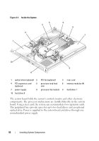
Figure 3-1.
Inside the System
The system board holds the system's control circuitry and other electronic
components. The processor and memory are installed directly on the system
board. Using a riser card, the system can accommodate two expansion cards.
The peripheral bays provide space for up to two hard drives and an optional
optical drive. Power is supplied to the system board and drives through one
nonredundant power supply.
1
optical drive (optional)
2
PCI fan (optional)
3
riser card
4
PCI expansion card
(optional)
5
processor and heat
sink
6
memory modules (4)
7
power supply
8
processor fan module
9
hard drive 1
10
hard drive 0
10
1
5
7
4
8
3
9
6
2