Dell PowerEdge R250 EMC Installation and Service Manual - Page 10
System information label
 |
View all Dell PowerEdge R250 manuals
Add to My Manuals
Save this manual to your list of manuals |
Page 10 highlights
5. Expansion card riser 7. System board 9. Information tag 6. Processor heat sink 8. Cooling fans Figure 6. Inside view of the cabled drive system 1. Optical drive 3. Intrusion switch 5. Expansion card riser 7. System board 9. Information tag 2. Cabled drive connector 4. Cabled power supply unit 6. Processor heat sink 8. Cooling fans System information label The system information label is located on the back of the system cover. Figure 7. Express service tag 10 PowerEdge R250 system overview
-
 1
1 -
2
-
3
-
4
-
 5
5 -
 6
6 -
 7
7 -
 8
8 -
 9
9 -
 10
10 -
 11
11 -
 12
12 -
 13
13 -
 14
14 -
 15
15 -
16
-
17
-
18
-
19
-
20
-
21
-
22
-
23
-
24
-
25
-
26
-
27
-
28
-
29
-
30
-
31
-
32
-
33
-
34
-
35
-
36
-
37
-
38
-
39
-
40
-
41
-
42
-
43
-
44
-
45
-
46
-
47
-
48
-
49
-
50
-
51
-
52
-
53
-
54
-
55
-
56
-
57
-
58
-
59
-
60
-
61
-
62
-
63
-
64
-
65
-
66
-
67
-
68
-
69
-
70
-
71
-
72
-
73
-
74
-
75
-
76
-
77
-
78
-
79
-
80
-
81
-
82
-
83
-
84
-
85
-
86
-
87
-
88
-
89
-
90
 |
 |

5.
Expansion card riser
6.
Processor heat sink
7.
System board
8.
Cooling fans
9.
Information tag
Figure 6. Inside view of the cabled drive system
1.
Optical drive
2.
Cabled drive connector
3.
Intrusion switch
4.
Cabled power supply unit
5.
Expansion card riser
6.
Processor heat sink
7.
System board
8.
Cooling fans
9.
Information tag
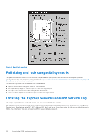
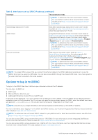
System information label
The system information label is located on the back of the system cover.
Figure 7. Express service tag
10
PowerEdge R250 system overview