Dell PowerEdge R250 EMC Installation and Service Manual - Page 72
System board, Removing the system board
 |
View all Dell PowerEdge R250 manuals
Add to My Manuals
Save this manual to your list of manuals |
Page 72 highlights
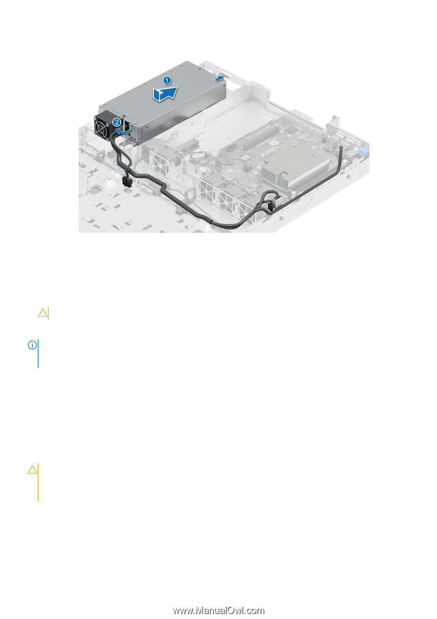
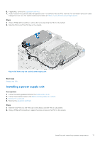
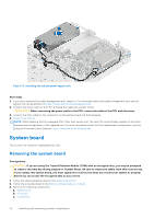
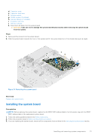
Figure 70. Installing the cabled power supply unit Next steps 1. If you have unlatched the cable management arm, relatch it. For information about the cable management arm, see the system rack documentation at https://www.dell.com/poweredgemanuals. 2. Connect the power cable to the PSU, and plug the cable into a power outlet. CAUTION: When connecting the power cable to the PSU, secure the cable to the PSU with the strap. 3. Connect the PSU cables to the connectors on the system board and the backplane. 4. Install the air shroud. NOTE: While replacing the hot swappable PSU, after next server boot; the new PSU automatically updates to the same firmware and configuration of the replaced one. For more information about the Part replacement configuration, see the Lifecycle Controller User's Guide at https://www.dell.com/idracmanuals System board This is a service technician replaceable part only. Removing the system board Prerequisites CAUTION: If you are using the Trusted Platform Module (TPM) with an encryption key, you may be prompted to create a recovery key during program or System Setup. Be sure to create and safely store this recovery key. If you replace this system board, you must supply the recovery key when you restart your system or program before you can access the encrypted data on your drives. 1. Follow the safety guidelines listed in the Safety instructions. 2. Follow the procedure listed in the Before working inside your system. 3. Remove the following components: a. System cover b. Air shroud c. Cooling fans 72 Installing and removing system components
-
 1
1 -
2
-
3
-
4
-
5
-
6
-
7
-
8
-
9
-
10
-
11
-
12
-
13
-
14
-
15
-
16
-
17
-
18
-
19
-
20
-
21
-
22
-
23
-
24
-
25
-
26
-
27
-
28
-
29
-
30
-
31
-
32
-
33
-
34
-
35
-
36
-
37
-
38
-
39
-
40
-
41
-
42
-
43
-
44
-
45
-
46
-
47
-
48
-
49
-
50
-
51
-
52
-
53
-
54
-
55
-
56
-
57
-
58
-
59
-
60
-
61
-
62
-
63
-
64
-
65
-
66
-
 67
67 -
 68
68 -
 69
69 -
 70
70 -
 71
71 -
 72
72 -
 73
73 -
 74
74 -
 75
75 -
 76
76 -
 77
77 -
78
-
79
-
80
-
81
-
82
-
83
-
84
-
85
-
86
-
87
-
88
-
89
-
90
 |
 |