Dell PowerEdge R250 EMC Installation and Service Manual - Page 54
Expansion card installation guidelines, Table 20. Expansion card riser configurations
 |
View all Dell PowerEdge R250 manuals
Add to My Manuals
Save this manual to your list of manuals |
Page 54 highlights
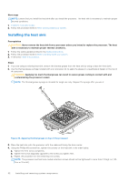
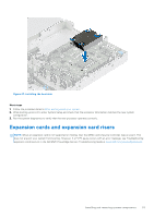
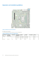
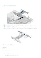
Expansion card installation guidelines Figure 48. Expansion card slot connectors 1. Butterfly riser connector The following table describes the expansion card riser configurations: Table 20. Expansion card riser configurations Configuratio Expansion PCIe Slots ns card risers Config 0 Butterfly riser 1 Controlling processor Processor 1 Height Half height 2 Processor 1 Half height Config 1 No riser N/a N/a N/a Length Half length Half length N/a Slot width Power x8 25 W x16 25 W N/a N/a 54 Installing and removing system components
-
 1
1 -
2
-
3
-
4
-
5
-
6
-
7
-
8
-
9
-
10
-
11
-
12
-
13
-
14
-
15
-
16
-
17
-
18
-
19
-
20
-
21
-
22
-
23
-
24
-
25
-
26
-
27
-
28
-
29
-
30
-
31
-
32
-
33
-
34
-
35
-
36
-
37
-
38
-
39
-
40
-
41
-
42
-
43
-
44
-
45
-
46
-
47
-
48
-
 49
49 -
 50
50 -
 51
51 -
 52
52 -
 53
53 -
 54
54 -
 55
55 -
 56
56 -
 57
57 -
 58
58 -
 59
59 -
60
-
61
-
62
-
63
-
64
-
65
-
66
-
67
-
68
-
69
-
70
-
71
-
72
-
73
-
74
-
75
-
76
-
77
-
78
-
79
-
80
-
81
-
82
-
83
-
84
-
85
-
86
-
87
-
88
-
89
-
90
 |
 |

Expansion card installation guidelines
Figure 48. Expansion card slot connectors
1.
Butterfly riser connector
The following table describes the expansion card riser configurations:
Table 20. Expansion card riser configurations
Configuratio
ns
Expansion
card risers
PCIe Slots
Controlling
processor
Height
Length
Slot width
Power
Config 0
Butterfly riser
1
Processor 1
Half height
Half length
x8
25 W
2
Processor 1
Half height
Half length
x16
25 W
Config 1
No riser
N/a
N/a
N/a
N/a
N/a
N/a
54
Installing and removing system components