Dell PowerEdge R250 EMC Installation and Service Manual - Page 43
Table 12. Cable routing - 4 x 3.5-inch backplane configuration with onboard SATA and PSU Bronze
 |
View all Dell PowerEdge R250 manuals
Add to My Manuals
Save this manual to your list of manuals |
Page 43 highlights
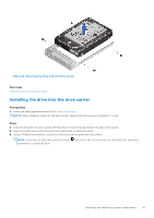
Figure 35. Cable routing for 4 x 3.5-inch backplane configuration with onboard SATA and PSU (Bronze) Table 12. Cable routing - 4 x 3.5-inch backplane configuration with onboard SATA and PSU (Bronze) From To BP_DST_SA1 (Signal connector on backplane) SL1_PCH_SA1 (Signal connector on system board) BP_PWR_1 (Power connector on backplane) Cabled power supply P1 (Power connecter 1) Cabled power supply P2 (Power connecter 2) Cabled power supply P3 (Power connecter 3) Cabled power supply Figure 36. Cable routing - 4 x 3.5-inch cabled drive configuration Installing and removing system components 43
-
 1
1 -
2
-
3
-
4
-
5
-
6
-
7
-
8
-
9
-
10
-
11
-
12
-
13
-
14
-
15
-
16
-
17
-
18
-
19
-
20
-
21
-
22
-
23
-
24
-
25
-
26
-
27
-
28
-
29
-
30
-
31
-
32
-
33
-
34
-
35
-
36
-
37
-
 38
38 -
 39
39 -
 40
40 -
 41
41 -
 42
42 -
 43
43 -
 44
44 -
 45
45 -
 46
46 -
 47
47 -
 48
48 -
49
-
50
-
51
-
52
-
53
-
54
-
55
-
56
-
57
-
58
-
59
-
60
-
61
-
62
-
63
-
64
-
65
-
66
-
67
-
68
-
69
-
70
-
71
-
72
-
73
-
74
-
75
-
76
-
77
-
78
-
79
-
80
-
81
-
82
-
83
-
84
-
85
-
86
-
87
-
88
-
89
-
90
 |
 |

Figure 35. Cable routing for 4 x 3.5-inch backplane configuration with onboard SATA and PSU (Bronze)
Table 12. Cable routing - 4 x 3.5-inch backplane configuration with onboard SATA and PSU (Bronze)
From
To
BP_DST_SA1 (Signal connector on backplane)
SL1_PCH_SA1 (Signal connector on system board)
BP_PWR_1 (Power connector on backplane)
Cabled power supply
P1 (Power connecter 1)
Cabled power supply
P2 (Power connecter 2)
Cabled power supply
P3 (Power connecter 3)
Cabled power supply
Figure 36. Cable routing - 4 x 3.5-inch cabled drive configuration
Installing and removing system components
43