Dell PowerEdge R250 EMC Installation and Service Manual - Page 42
Cable routing
 |
View all Dell PowerEdge R250 manuals
Add to My Manuals
Save this manual to your list of manuals |
Page 42 highlights
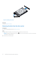
Figure 33. Installing a drive into the drive carrier Next steps 1. Install the drive carrier. Cable routing Figure 34. Cable routing - 4 x 3.5-inch backplane configuration with PERC adapter Table 11. Cable routing - 4 x 3.5-inch backplane configuration with PERC adapter From To BP_PWR_1 (Power connector on backplane) HDD/ODD_PWR (PIB connector on the system board) CTRL_SRC_SA1 (Signal connector on the PERC) BP_DST_SA1 (Signal connector on backplane) 42 Installing and removing system components
-
 1
1 -
2
-
3
-
4
-
5
-
6
-
7
-
8
-
9
-
10
-
11
-
12
-
13
-
14
-
15
-
16
-
17
-
18
-
19
-
20
-
21
-
22
-
23
-
24
-
25
-
26
-
27
-
28
-
29
-
30
-
31
-
32
-
33
-
34
-
35
-
36
-
 37
37 -
 38
38 -
 39
39 -
 40
40 -
 41
41 -
 42
42 -
 43
43 -
 44
44 -
 45
45 -
 46
46 -
 47
47 -
48
-
49
-
50
-
51
-
52
-
53
-
54
-
55
-
56
-
57
-
58
-
59
-
60
-
61
-
62
-
63
-
64
-
65
-
66
-
67
-
68
-
69
-
70
-
71
-
72
-
73
-
74
-
75
-
76
-
77
-
78
-
79
-
80
-
81
-
82
-
83
-
84
-
85
-
86
-
87
-
88
-
89
-
90
 |
 |

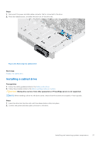
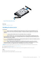
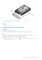
Figure 33. Installing a drive into the drive carrier
Next steps
1.
Install the drive carrier
.
Cable routing
Figure 34. Cable routing - 4 x 3.5-inch backplane configuration with PERC adapter
Table 11. Cable routing - 4 x 3.5-inch backplane configuration with PERC adapter
From
To
BP_PWR_1 (Power connector on backplane)
HDD/ODD_PWR (PIB connector on the system board)
CTRL_SRC_SA1 (Signal connector on the PERC)
BP_DST_SA1 (Signal connector on backplane)
42
Installing and removing system components