Dell PowerEdge R250 EMC Installation and Service Manual - Page 47
General memory module installation guidelines, Removing a memory module
 |
View all Dell PowerEdge R250 manuals
Add to My Manuals
Save this manual to your list of manuals |
Page 47 highlights
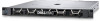
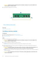
Table 18. Supported memory matrix DIMM type Rank Capacity UDIMM 1R 2R 8 GB /16 GB 32 GB DIMM rated voltage and speed DIMMs per Channel (DPC) DDR4 (1.2 V), 3200 MT/s 3200 MT/s DDR4 (1.2 V), 3200 MT/s 3200 MT/s General memory module installation guidelines To ensure optimal performance of your system, observe the following general guidelines when configuring your system memory. If your system's memory configurations fail to observe these guidelines, your system might not boot, stop responding during memory configuration, or operate with reduced memory. The memory bus may operate at speeds up to 2933 MT/s depending on the following factors: ● System profile selected (for example, Performance Optimized, or Custom [can be run at high speed or lower]) ● Maximum supported DIMM speed of the processor ● Maximum supported speed of the DIMMs ● Rank of the DIMMs NOTE: MT/s indicates DIMM speed in Mega-Transfers per second. The system supports Flexible Memory Configuration, enabling the system to be configured and run in any valid chipset architectural configuration. The following are the recommended guidelines for installing memory modules: ● All DIMMs must be DDR4. ● If memory modules with different speeds are installed, they operate at the speed of the slowest installed memory module. ● Populate memory module sockets only if a processor is installed. ○ For single-processor systems, sockets A1 to A4 is available. ● In Optimizer Mode, the DRAM controllers operate independently in the 64-bit mode and provide optimized memory performance. NOTE: DIMM speed is limited to 2933 MT/s when mixing dual rank DIMMs with single rank or dual rank DIMMs in the same channel. Table 19. Memory population rules Processor Configuration Memory population Memory population information Single processor Optimizer (Independent channel) population order A{1}, A{2}, A{3}, A{4} 1, 2, 3, 4 DIMMs are allowed. ● Populate all the sockets with white release tabs first, followed by the black release tabs. ● Unbalanced or odd memory configuration results in a performance loss and system may not identify the memory modules being installed, so always populate memory channels identically with equal DIMMs for best performance. Removing a memory module Prerequisites 1. Follow the safety guidelines listed in the Safety instructions. 2. Follow the procedure listed in the Before working inside your system. 3. Remove the air shroud. WARNING: The memory modules are hot to touch for some time after the system has been powered off. Allow the memory modules to cool before handling them. Steps 1. Locate the appropriate memory module socket. 2. To release the memory module from the socket, simultaneously press the ejectors on both ends of the memory module socket to fully open. Installing and removing system components 47
-
 1
1 -
2
-
3
-
4
-
5
-
6
-
7
-
8
-
9
-
10
-
11
-
12
-
13
-
14
-
15
-
16
-
17
-
18
-
19
-
20
-
21
-
22
-
23
-
24
-
25
-
26
-
27
-
28
-
29
-
30
-
31
-
32
-
33
-
34
-
35
-
36
-
37
-
38
-
39
-
40
-
41
-
 42
42 -
 43
43 -
 44
44 -
 45
45 -
 46
46 -
 47
47 -
 48
48 -
 49
49 -
 50
50 -
 51
51 -
 52
52 -
53
-
54
-
55
-
56
-
57
-
58
-
59
-
60
-
61
-
62
-
63
-
64
-
65
-
66
-
67
-
68
-
69
-
70
-
71
-
72
-
73
-
74
-
75
-
76
-
77
-
78
-
79
-
80
-
81
-
82
-
83
-
84
-
85
-
86
-
87
-
88
-
89
-
90
 |
 |
