Dell PowerEdge R250 EMC Installation and Service Manual - Page 46
System memory, System memory guidelines
 |
View all Dell PowerEdge R250 manuals
Add to My Manuals
Save this manual to your list of manuals |
Page 46 highlights
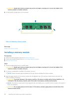
Table 16. Cable routing - 2 x 3.5-inch cable drive configuration with SATA connection From To HDD0 (HDD0 signal connector) SL1_PCH_SA1 (Signal connector on system board) HDD1 (HDD1 signal connector) SL1_PCH_SA1 (Signal connector on system board) Power connector on HDD0 and HDD1 PIB_CONNECTOR (PIB connector on system board) ODD (Optical Disk Drive) connector HDD/ODD_PWR (HDD/ODD power connector on system board) System memory System memory guidelines The PowerEdge R250 system supports DDR4 unregistered DIMMs (UDIMMs). System memory holds the instructions that are executed by the processor. Your system contains four memory sockets that are organized into two channels. In each channel, the first socket is marked white and the second socket black. Memory channels are organized as follows: Table 17. Memory channels Channel 0 A1 and A3 Channel 1 A2 and A4 Figure 40. Memory socket location 46 Installing and removing system components
-
 1
1 -
2
-
3
-
4
-
5
-
6
-
7
-
8
-
9
-
10
-
11
-
12
-
13
-
14
-
15
-
16
-
17
-
18
-
19
-
20
-
21
-
22
-
23
-
24
-
25
-
26
-
27
-
28
-
29
-
30
-
31
-
32
-
33
-
34
-
35
-
36
-
37
-
38
-
39
-
40
-
 41
41 -
 42
42 -
 43
43 -
 44
44 -
 45
45 -
 46
46 -
 47
47 -
 48
48 -
 49
49 -
 50
50 -
 51
51 -
52
-
53
-
54
-
55
-
56
-
57
-
58
-
59
-
60
-
61
-
62
-
63
-
64
-
65
-
66
-
67
-
68
-
69
-
70
-
71
-
72
-
73
-
74
-
75
-
76
-
77
-
78
-
79
-
80
-
81
-
82
-
83
-
84
-
85
-
86
-
87
-
88
-
89
-
90
 |
 |
