HP Integrity rx2800 Installation Guide - Page 12
Server block diagram, Front I/O connector
 |
View all HP Integrity rx2800 manuals
Add to My Manuals
Save this manual to your list of manuals |
Page 12 highlights
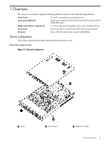
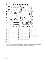
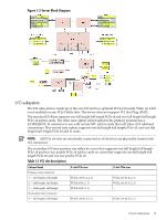
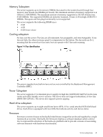
Figure 1-2 System board components 1 Memory riser connector 10 SD card slot 19 Memory expansion board 1 11 system battery connector 4 2 Memory riser connector 12 SAS B connector 20 Fan 6 connector 2 13 SAS A connector 21 Fan 5 connector 3 Processor socket 0 14 Secondary riser connector 22 Fan 4 connector 4 Processor socket 1 15 SAS cache module 23 Fan 3 connector 5 Processor 0 power connector 24 Internal USB connector connector 16 SAS power connector 25 Fan 2 connector 6 SATA optical drive connector 7 Front I/O connector 17 Processor 1 power 26 Fan 1 connector connector 18 Memory expansion board 8 Primary riser connector connector 3 9 TPM connector Server block diagram Figure 1-3 is a block diagram of the main server subsystems. It illustrates the main components of each subsystem and how the subsystems are connected to one another. 12 Overview
-
 1
1 -
2
-
3
-
4
-
5
-
6
-
 7
7 -
 8
8 -
 9
9 -
 10
10 -
 11
11 -
 12
12 -
 13
13 -
 14
14 -
 15
15 -
 16
16 -
 17
17 -
18
-
19
-
20
-
21
-
22
-
23
-
24
-
25
-
26
-
27
-
28
-
29
-
30
-
31
-
32
-
33
-
34
-
35
-
36
-
37
-
38
-
39
-
40
-
41
-
42
-
43
-
44
-
45
-
46
-
47
-
48
-
49
-
50
-
51
-
52
-
53
-
54
-
55
-
56
-
57
-
58
-
59
-
60
-
61
-
62
-
63
-
64
-
65
-
66
-
67
-
68
-
69
 |
 |
