HP Integrity rx2800 Installation Guide - Page 45
Pedestal kit installation, Connecting Server Cables, AC Input Power, Power States
 |
View all HP Integrity rx2800 manuals
Add to My Manuals
Save this manual to your list of manuals |
Page 45 highlights
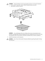
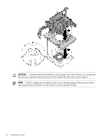
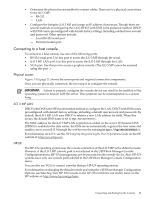
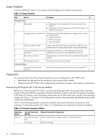
The guide is located on the HP website at: http://www.hp.com/racksolutions on the HP Integrity and HP 9000 Servers infrastructure page. Click the Rack Systems/E link. Select Mounting information from the menu, then select the guide titled Mounting in non-HP racks. Pedestal kit installation The server ships with a pedestal mount if you order the rackless configuration option. The pedestal mount is packaged in a separate carton which is attached to the server carton. To change the server from a rack mount to a rackless configuration, you need a pedestal kit. The pedestal mount kit comes with the Pedestal Kit Installation Guide for HP Integrity rx2800 i2 and HP Proliant DL380 G6 & DL385 G6 Servers. Follow the steps in this installation guide to attach the pedestal to the server. Connecting Server Cables This section describes the cables to connect to power the server and to provide LAN connectivity for the server. AC Input Power The server can receive AC input from two different AC power sources. The power receptacles are located at the rear of the server. A maximum of two power supplies can be installed in the server. Installing two power supplies in the server provides 1+1 redundancy, meaning that if one power supply fails, there is still enough power supplied to the server to operate. You must promptly replace the failed power supply to restore 1+1 functionality. All high line (220V) configs are capable of 1+1 redundancy. Low line (110V) configurations can maintain 1+1 redundancy as long as the total power consumed does not exceed 800W. A minimum of one power supply is required to power the server. If only one power supply is installed in the server, there is no 1+1 capability. Power States The server has three power states: • Standby power • Full power • Off Table 2-4 lists the server power states. Table 2-4 Power States Power States Standby power Full power Off Power Cable Plugged Into Receptacle? Yes Yes No Power Activated through the iLO 3 MP PC Standby DC Command; or Front Panel Power Button Voltage Activated? Applied? No Yes Yes Yes No No DC Voltage Applied? No Yes No Connecting Server Cables 45
-
 1
1 -
2
-
3
-
4
-
5
-
6
-
7
-
8
-
9
-
10
-
11
-
12
-
13
-
14
-
15
-
16
-
17
-
18
-
19
-
20
-
21
-
22
-
23
-
24
-
25
-
26
-
27
-
28
-
29
-
30
-
31
-
32
-
33
-
34
-
35
-
36
-
37
-
38
-
39
-
 40
40 -
 41
41 -
 42
42 -
 43
43 -
 44
44 -
 45
45 -
 46
46 -
 47
47 -
 48
48 -
 49
49 -
 50
50 -
51
-
52
-
53
-
54
-
55
-
56
-
57
-
58
-
59
-
60
-
61
-
62
-
63
-
64
-
65
-
66
-
67
-
68
-
69
 |
 |