HP Integrity rx2800 Installation Guide - Page 34
DIMMs, Memory configurations, Memory riser board locations and slot IDs
 |
View all HP Integrity rx2800 manuals
Add to My Manuals
Save this manual to your list of manuals |
Page 34 highlights
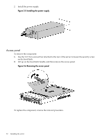
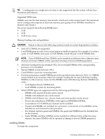
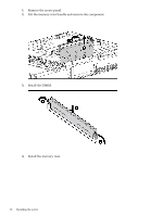
DIMMs Memory configurations The server has 24 system memory DIMM slots located on four memory riser boards (six DIMMs per riser). You can access the memory riser boards without removing the airflow guide or the I/O card cage. The DIMMs are partitioned by the number of processors installed into the server. If you have one processor installed in the system, you can only use 12 of the 24 memory slots. CAUTION: Observe all ESD safety precautions before attempting this procedure. Failure to follow ESD safety precautions can result in damage to the server. Memory riser board locations and slot IDs Install DIMMs into the appropriate risers attached to the system board; each slot has a unique ID. See Figure 1-2 "System board components " for memory riser locations. Figure 2-7 DIMM slot IDs Table 2-2 Memory Load Order Pair Number 1 2 3 4 5 6 7 8 9 10 11 12 2 CPU System (socket 0 and 1) Riser Memory Slots Riser 1 3A and 4A Riser 3 3A and 4A Riser 2 3A and 4A Riser 4 3A and 4A Riser 1 1B and 6B Riser 3 1B and 6B Riser 2 1B and 6B Riser 4 1B and 6B Riser 1 2C and 5C Riser 3 2C and 5C Riser 2 2C and 5C Riser 4 2C and 5C 1 CPU System (socket 0) Riser Memory Slots Riser 1 3A and 4A Riser 2 3A and 4A Riser 1 1B and 6B Riser 2 1B and 6B Riser 1 2C and 5C Riser 2 2C and 5C - - - - - - - - - - - - 34 Installing the server
-
 1
1 -
2
-
3
-
4
-
5
-
6
-
7
-
8
-
9
-
10
-
11
-
12
-
13
-
14
-
15
-
16
-
17
-
18
-
19
-
20
-
21
-
22
-
23
-
24
-
25
-
26
-
27
-
28
-
 29
29 -
 30
30 -
 31
31 -
 32
32 -
 33
33 -
 34
34 -
 35
35 -
 36
36 -
 37
37 -
 38
38 -
 39
39 -
40
-
41
-
42
-
43
-
44
-
45
-
46
-
47
-
48
-
49
-
50
-
51
-
52
-
53
-
54
-
55
-
56
-
57
-
58
-
59
-
60
-
61
-
62
-
63
-
64
-
65
-
66
-
67
-
68
-
69
 |
 |
