HP Integrity rx2800 Installation Guide - Page 22
Power supply
 |
View all HP Integrity rx2800 manuals
Add to My Manuals
Save this manual to your list of manuals |
Page 22 highlights
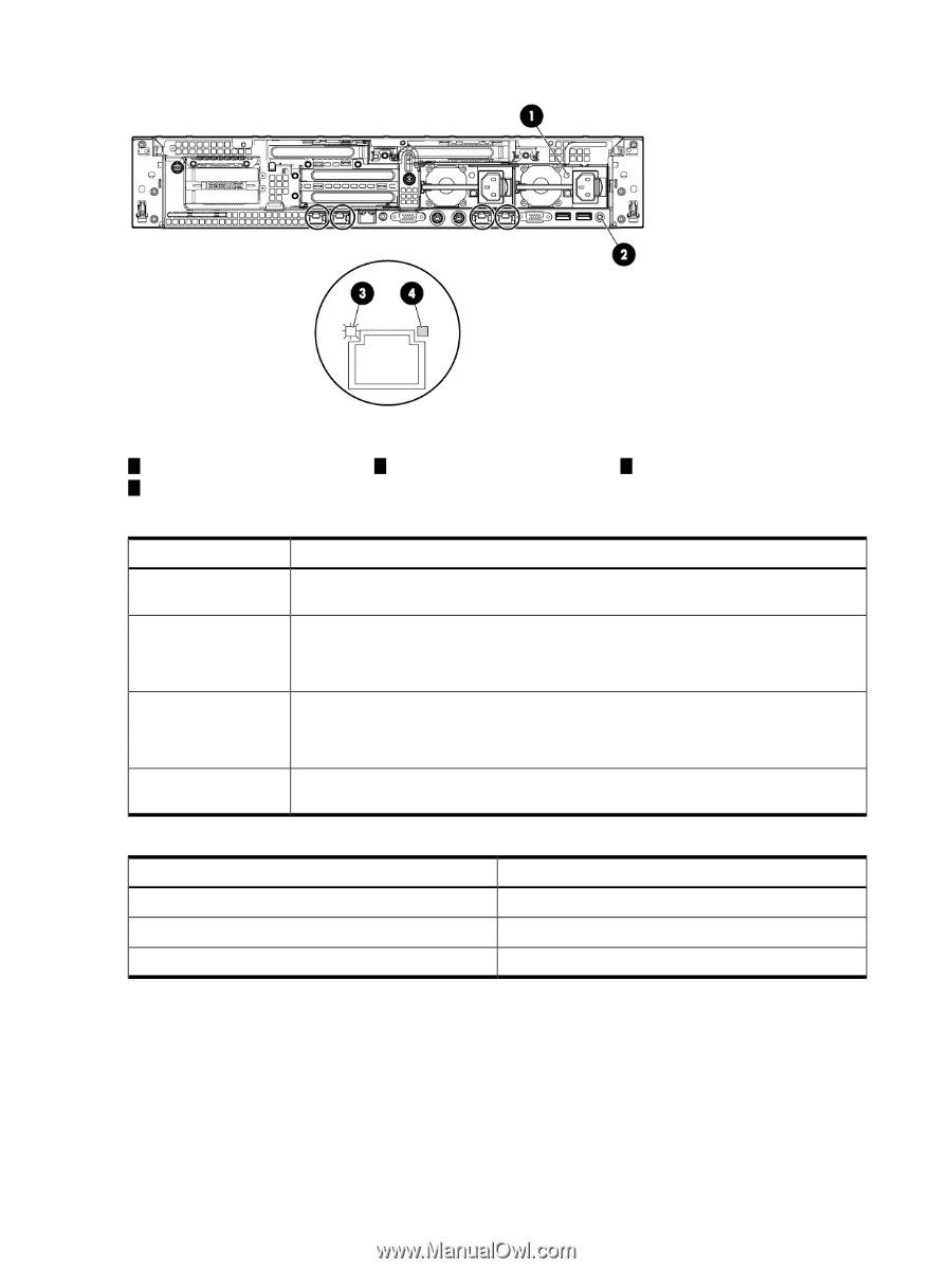
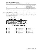
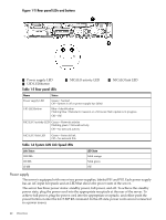
Figure 1-11 Rear panel LEDs and buttons 1 Power supply LED 2 UID LED/button Table 1-5 Rear panel LEDs 3 NIC/iLO activity LED 4 NIC/iLO link LED Name Power supply LED UID LED/button Status Green = Normal Off = System is off or power supply has failed Blue = Identification Flashing blue = Remote iLO session or a firmware flash update is in progress Off = Off NIC/iLO 3 activity LED Green = Network activity Flashing green = Network activity Off = No network activity NIC/iLO 3 link LED Green = Network link Off = No network link Table 1-6 System LAN Link Speed LEDs Link Status 1000 Mb 100 Mb 10 Mb LED State Solid orange Solid green Off Power supply The server is equipped with one or two power supplies, labeled PS1 and PS2. Each power supply has an AC input receptacle and an LED that shows the power state of the server. The server has three power states: standby power, full power, and off. To achieve the standby power state, plug the power cord into the appropriate receptacle at the rear of the server. To achieve full power, plug the power cord into the appropriate receptacle, and either push the power button or enter the iLO 3 MP PC command. In the off state, power cords are not connected to a power source 22 Overview
-
 1
1 -
2
-
3
-
4
-
5
-
6
-
7
-
8
-
9
-
10
-
11
-
12
-
13
-
14
-
15
-
16
-
 17
17 -
 18
18 -
 19
19 -
 20
20 -
 21
21 -
 22
22 -
 23
23 -
 24
24 -
 25
25 -
 26
26 -
 27
27 -
28
-
29
-
30
-
31
-
32
-
33
-
34
-
35
-
36
-
37
-
38
-
39
-
40
-
41
-
42
-
43
-
44
-
45
-
46
-
47
-
48
-
49
-
50
-
51
-
52
-
53
-
54
-
55
-
56
-
57
-
58
-
59
-
60
-
61
-
62
-
63
-
64
-
65
-
66
-
67
-
68
-
69
 |
 |