HP Integrity rx2800 Installation Guide - Page 13
I/O subsystem, Server Block Diagram, Table 1-1 PCI slot descriptions
 |
View all HP Integrity rx2800 manuals
Add to My Manuals
Save this manual to your list of manuals |
Page 13 highlights
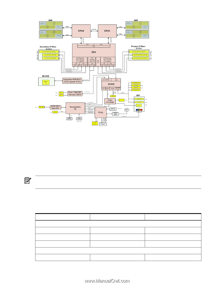
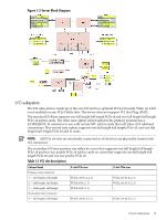
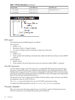
Figure 1-3 Server Block Diagram I/O subsystem The I/O subsystem is made up of the core I/O and two optional I/O riser boards. Wake on LAN is not enabled on any PCIe Public slots. The server does not support PCI Hot Plug (PHP). The standard I/O Riser supports one full height full length PCIe x8 and two full height half length PCIe x4 add in cards. The other riser option when loaded in the primary position has a iLO/RMII/NC-SI connector to use with certain NIC add in cards that will allow iLO sideband connections. This second riser option supports one full height full length PCIe x8, and one full height half length PCIe x8 add in cards. NOTE: All PCIe x8 slots are electrically connected as x8 slots but are physically loaded with x16 connectors. The secondary I/O riser position can either be a riser that supports one full height full length PCIe x8 and two low profile PCIe x4 add in cards or a riser that supports one full height full length PCIe x8 and one low profile PCIe x8. Table 1-1 PCI slot descriptions Column Head Primary riser connector 1 - full length, full height 2 - half length, full height 3 - half length, full height Secondary riser connector 4 - full length, full heigth 3-slot PCIe riser PCIe2 x16 (8, 4, 2, 1) PCIe2 x8 (4, 2, 1) PCIe2 x8 (4, 2, 1) PCIe2 x16 (8, 4, 2, 1) 2-slot PCIe riser PCIe2 x16 (8, 4, 2, 1) PCIe2 x16 (8, 4, 2, 1) - PCIe2 x16 (8, 4, 2, 1) Server subsystems 13
-
 1
1 -
2
-
3
-
4
-
5
-
6
-
7
-
 8
8 -
 9
9 -
 10
10 -
 11
11 -
 12
12 -
 13
13 -
 14
14 -
 15
15 -
 16
16 -
 17
17 -
 18
18 -
19
-
20
-
21
-
22
-
23
-
24
-
25
-
26
-
27
-
28
-
29
-
30
-
31
-
32
-
33
-
34
-
35
-
36
-
37
-
38
-
39
-
40
-
41
-
42
-
43
-
44
-
45
-
46
-
47
-
48
-
49
-
50
-
51
-
52
-
53
-
54
-
55
-
56
-
57
-
58
-
59
-
60
-
61
-
62
-
63
-
64
-
65
-
66
-
67
-
68
-
69
 |
 |