HP Rp5700 HP rp5700 Business System Service Reference Guide, 1st Edition
HP Rp5700 - Point of Sale System Manual
 |
UPC - 884420470731
View all HP Rp5700 manuals
Add to My Manuals
Save this manual to your list of manuals |
HP Rp5700 manual content summary:
- HP Rp5700 | HP rp5700 Business System Service Reference Guide, 1st Edition - Page 1
Service Reference Guide HP rp5700 Business System - HP Rp5700 | HP rp5700 Business System Service Reference Guide, 1st Edition - Page 2
protected by copyright. No part of this document may be photocopied, reproduced, or translated to another language without the prior written consent of Hewlett-Packard Company. Service Reference Guide HP rp5700 Business System Second Edition (December 2009) First Edition (April 2006) Document Part - HP Rp5700 | HP rp5700 Business System Service Reference Guide, 1st Edition - Page 3
About This Book WARNING! Text set off in this manner indicates that failure to follow directions could result in bodily harm or loss of life. CAUTION: Text set off in this manner indicates that failure to follow directions could result in damage to equipment or loss of information. NOTE: Text set - HP Rp5700 | HP rp5700 Business System Service Reference Guide, 1st Edition - Page 4
iv About This Book ENWW - HP Rp5700 | HP rp5700 Business System Service Reference Guide, 1st Edition - Page 5
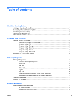
contents 1 Install the Operating System Installing or Upgrading Device Drivers 1 Downloading Microsoft Windows Updates 2 Transferring Files and Settings ...2 Creating a Disc Recovery Set ...2 2 Computer Setup (F10) Utility Computer Setup (F10) Utilities ...5 Using Computer Setup (F10) Utilities - HP Rp5700 | HP rp5700 Business System Service Reference Guide, 1st Edition - Page 6
Device 37 Dual-State Power Button ...38 HP Web Site Support ...38 Industry Standards ...39 Asset Tracking and Security ...39 Password Security ...41 Establishing a Setup Password Using Computer Setup 42 Establishing a Power-On Password Using Computer Setup 42 Entering a Power-On Password 42 - HP Rp5700 | HP rp5700 Business System Service Reference Guide, 1st Edition - Page 7
...56 Routine Care ...57 General Cleaning Safety Precautions 57 Cleaning the Computer Case 57 Cleaning the Keyboard ...57 Cleaning the Monitor ...58 Cleaning the Mouse ...58 Service Considerations ...58 Power Supply Fan ...58 Tools and Software Requirements 58 Screws ...59 Cables and Connectors - HP Rp5700 | HP rp5700 Business System Service Reference Guide, 1st Edition - Page 8
Hard Drive 100 Fan Shroud ...103 Chassis Fan ...104 Power Switch ...105 Front USB Connector ...106 Speaker ...107 Heatsink ...108 Processor ...109 Power Supply ...111 System Board ...112 Battery ...113 Type 1 Battery Holder ...114 Type 2 Battery Holder ...114 Type 3 Battery Holder ...115 viii - HP Rp5700 | HP rp5700 Business System Service Reference Guide, 1st Edition - Page 9
127 Japanese Power Cord Requirements 127 Country-Specific Requirements ...128 Appendix C POST Error Messages Power-On Self-Test (POST) ...129 POST Numeric Codes and Text Messages 130 Interpreting POST Diagnostic Front Panel LEDs and Audible Codes 136 Appendix D Troubleshooting Without Diagnostics - HP Rp5700 | HP rp5700 Business System Service Reference Guide, 1st Edition - Page 10
Memory Problems ...165 Solving Processor Problems ...166 Solving CD-ROM and DVD Problems 166 Solving Drive Key Problems ...169 Solving Front Panel Component Problems 170 Solving Internet Access Problems ...171 Solving Software Problems ...173 Contacting Customer Support ...174 Appendix E System - HP Rp5700 | HP rp5700 Business System Service Reference Guide, 1st Edition - Page 11
path specification with C:\i386, or use the Browse button in the dialog box to locate the i386 folder. This action points the operating system to the appropriate drivers. Obtain the latest support software, including support software for the operating system from http://www.hp.com/support. Select - HP Rp5700 | HP rp5700 Business System Service Reference Guide, 1st Edition - Page 12
Click on the Windows Update link. In Microsoft Windows XP, you will be directed to the Microsoft Windows Update Web site. If you see one or more pop-up windows that ask you to install a program from http://www.microsoft.com, click Yes to install the program. Follow the instructions on the Microsoft - HP Rp5700 | HP rp5700 Business System Service Reference Guide, 1st Edition - Page 13
can access a user manual at Start > HP Backup and Recovery > HP Backup and Recovery Manager Manual. NOTE: If Create factory software recovery CDs or DVDs to recover the system is unavailable on the system, the HP Restore Plus CD set can be obtained through product support on http://welcome/ country - HP Rp5700 | HP rp5700 Business System Service Reference Guide, 1st Edition - Page 14
4 Chapter 1 Install the Operating System ENWW - HP Rp5700 | HP rp5700 Business System Service Reference Guide, 1st Edition - Page 15
Use Computer Setup (F10) Utility to do the following: ● Change factory default settings. ● Set the system date and time. ● Set, view, change, or verify the system configuration, including settings for processor, graphics, memory, audio, storage, communications, and input devices. ● Modify the boot - HP Rp5700 | HP rp5700 Business System Service Reference Guide, 1st Edition - Page 16
appropriate time, you must restart the computer and again press F10 when the monitor Computer Setup-Security on page 11 Power Table 2-5 Computer Setup-Power on page 13 Advanced Table 2-6 Computer Setup-Advanced (for advanced users) on page 14 NOTE: Support for specific Computer Setup options - HP Rp5700 | HP rp5700 Business System Service Reference Guide, 1st Edition - Page 17
● Installed memory size/speed, number of channels (single or dual) (if applicable) ● Integrated MAC address for embedded, enabled NIC (if applicable) ● System BIOS (includes family name and version) ● Chassis serial number ● Asset tracking number About Displays copyright notice. Set Time and Date - HP Rp5700 | HP rp5700 Business System Service Reference Guide, 1st Edition - Page 18
and options are displayed. The following options may be presented. Hard Disk ● None (prevents BIOS data accesses and disables it as a boot device system or an application) into terms the hard drive can accept. Logical cylinders may not exceed 1024. The number of heads may not exceed 256. The number - HP Rp5700 | HP rp5700 Business System Service Reference Guide, 1st Edition - Page 19
and dx7300 Business Desktops Using Intel Matrix Storage Manager at http://www.hp.com/support. Select your country and language, select See support and troubleshooting information, enter the model number of the computer, and press Enter. In the Resources category, click Manuals (guides, supplements - HP Rp5700 | HP rp5700 Business System Service Reference Guide, 1st Edition - Page 20
apply after a non-MS-DOS operating system has started. Shortcut to Temporarily Override Boot Order To boot one time from a device other than the default device specified in Boot Order, restart the computer and press F9 when the monitor light turns green. After POST is completed, a list of bootable - HP Rp5700 | HP rp5700 Business System Service Reference Guide, 1st Edition - Page 21
the user does not enter the correct power-on password, the unit will not boot. NOTE: This password does not appear on warm boots , such as Ctrl + Alt + Delete or Restart from Windows, unless enabled in Password Options, below. See the Troubleshooting Guide on the Documentation and Diagnostics CD - HP Rp5700 | HP rp5700 Business System Service Reference Guide, 1st Edition - Page 22
(continued) Network Service Boot Enables/disables the computer's ability to boot from an operating system installed on a network server. (Feature available on NIC models only; the network controller must be either a PCI expansion card or embedded on the system board.) System IDs Allows you - HP Rp5700 | HP rp5700 Business System Service Reference Guide, 1st Edition - Page 23
S5 both have the LED off. S1 (no longer supported) and S3 use 1 blink per second. ● S5 Maximum Power Savings (some models)-Enable/Disable. Enabling this feature reduces the power of this system as much as possible in the S5 state. Power is removed from the wake up circuitry, the expansion slots, and - HP Rp5700 | HP rp5700 Business System Service Reference Guide, 1st Edition - Page 24
that they are not ready to boot by the time POST is finished. The POST delay also gives you more time to select F10 to enter Computer (F10) Setup. ● I/O APIC Mode (some models) (enable/disable). Enabling this feature will allow Microsoft® Windows Operating Systems to run optimally. This feature must - HP Rp5700 | HP rp5700 Business System Service Reference Guide, 1st Edition - Page 25
continued) Execute Memory Test Restarts the computer and executes the POST memory test. (some models) BIOS Power-On Allows you to set the computer to turn on automatically at a time you specify. Onboard Devices PCI Devices Allows you to set resources for or disable onboard system devices (serial - HP Rp5700 | HP rp5700 Business System Service Reference Guide, 1st Edition - Page 26
Settings This method of recovery requires that you first perform the Save to Removable Media command with the Computer Setup (F10) Utility before Restore is needed. (See Save to Removable Media on page 7 in the Computer Setup-File table.) NOTE: It is recommended that you save any modified - HP Rp5700 | HP rp5700 Business System Service Reference Guide, 1st Edition - Page 27
Computer Setup (F10) Utility Guide on the Documentation and Diagnostics CD for more information. You can also change the boot order so that the system boots to the optical derive on a one-time basis by pressing the F9 key at startup 4. Select the appropriate language and click Continue. ENWW HP - HP Rp5700 | HP rp5700 Business System Service Reference Guide, 1st Edition - Page 28
Provides system BIOS and PCI device information. Asset Control-Shows product name, asset tag, system serial number, and processor information. Communication-Shows information about the computer parallel (LPT) and serial (COM) port settings, plus USB and network controller information. Graphics-Shows - HP Rp5700 | HP rp5700 Business System Service Reference Guide, 1st Edition - Page 29
display prompts and requires no interaction. If errors are found, they are displayed when testing Number of Loops or Total Test Time. When choosing to run the test over a specified number of loops, enter the number The Status tab, which allows you to monitor the progress of the test, is automatically - HP Rp5700 | HP rp5700 Business System Service Reference Guide, 1st Edition - Page 30
the failed hardware. ● The Failed Count is the number of times the device has failed a test. ● The Error Code provides a numerical code for the failure. The error codes are defined in the Help tab. The Clear Error Log button will clear the contents of the Error Log. Help Tab On the Help tab contains - HP Rp5700 | HP rp5700 Business System Service Reference Guide, 1st Edition - Page 31
drive. Downloading the Latest Version of HP Insight Diagnostics 1. Go to http://www.hp.com. 2. Click the Software & Driver Downloads link. 3. Enter your product number (for example, rp5700) in the text box and press the Enter key. 4. Select your specific computer model. 5. Select your OS. 6. Click - HP Rp5700 | HP rp5700 Business System Service Reference Guide, 1st Edition - Page 32
NOTE: For more information on using HP Backup and Recovery Manager, refer to the HP Backup and Recovery Manager User Guide by selecting Start > HP Backup and Recovery > HP Backup and Recovery Manager Manual. 22 Chapter 3 HP Insight Diagnostics ENWW - HP Rp5700 | HP rp5700 Business System Service Reference Guide, 1st Edition - Page 33
and features of desktop management are: ● Initial configuration and deployment ● Remote system installation ● Software updating and management ● ROM flash ● Asset tracking and security ● Fault notification and recovery NOTE: Support for specific features described in this guide may vary by - HP Rp5700 | HP rp5700 Business System Service Reference Guide, 1st Edition - Page 34
with recovery of system software, configuration management and troubleshooting, and power management. NOTE: See HP Backup and Recovery Manageron page 25 for information on creating the Restore Plus! CD. HP OpenView Agent NOTE: HP OpenView Agent is not currently available for Windows Vista. The Radia - HP Rp5700 | HP rp5700 Business System Service Reference Guide, 1st Edition - Page 35
Manager Manual. We suggest that you print this document for easy reference in case of future emergency. If Create factory software recovery CDs or DVDs to recover the system is unavailable on your system, the HP Restore Plus! CD set can be obtained through product support on http://welcome.hp.com - HP Rp5700 | HP rp5700 Business System Service Reference Guide, 1st Edition - Page 36
PCs ● Remotely updating the system BIOS in flash ROM (Remote ROM Flash on page 32) ● Configuring the system BIOS settings To initiate Remote System Installation, press F12 when the F12 = Network Service Boot message appears in the lower-right corner of the HP logo screen when the computer is booting - HP Rp5700 | HP rp5700 Business System Service Reference Guide, 1st Edition - Page 37
passwords and computer boot order remotely from your system management console on any or all of your client systems without having to visit each machine. HP System Software Manager HP System Software Manager (SSM) is a free utility that automates remote deployment of device drivers and BIOS updates - HP Rp5700 | HP rp5700 Business System Service Reference Guide, 1st Edition - Page 38
Use HP Client Manager to: ● Get valuable hardware information such as CPU, memory, video, and security settings ● Monitor system health to fix problems before they occur ● Automatically acquire and install drivers and BIOS updates without visiting each PC ● Remotely configure BIOS and security - HP Rp5700 | HP rp5700 Business System Service Reference Guide, 1st Edition - Page 39
: ● The Basic Edition is a free product for managing HP desktops, notebooks, and workstations, providing hardware and software inventory, remote control, HP alert monitoring, HP BIOS and driver updates, integration with HP Protect Tools and add-on support for Intel AMT. The Basic edition also - HP Rp5700 | HP rp5700 Business System Service Reference Guide, 1st Edition - Page 40
productivity for the managed organization. HP now offers a mechanism to streamline updates for HP systems within a Microsoft System Management Server management infrastructure. The HP Client Catalog for SMS contains software driver and patch information for desktop, mobile and workstation platforms - HP Rp5700 | HP rp5700 Business System Service Reference Guide, 1st Edition - Page 41
. For HP-specific information on Intel vPro technology, see the white papers at http://www.hp.com/ support. Select your country and language, select See support and troubleshooting information, enter the model number of the computer, and press Enter. In the Resources category, click Manuals (guides - HP Rp5700 | HP rp5700 Business System Service Reference Guide, 1st Edition - Page 42
ROM from being unintentionally updated or overwritten. This is important to ensure the operating integrity of the computer. Should you need or want to upgrade the BIOS, you may download the latest BIOS images from the HP driver and support page, http:/www.hp.com/support/files. CAUTION: For maximum - HP Rp5700 | HP rp5700 Business System Service Reference Guide, 1st Edition - Page 43
is used to locally update or restore the system BIOS of individual PCs from a Windows operating system. For more information on HPQFlash, visit http://www.hp.com/support/files and enter the model number of the computer when prompted. Boot Block Emergency Recovery Mode Boot Block Emergency Recovery - HP Rp5700 | HP rp5700 Business System Service Reference Guide, 1st Edition - Page 44
Click File > Replicated Setup > Restore from Removable Media, and follow the instructions on the screen. 11. Restart the computer when the configuration is complete. Copying to Multiple Computers CAUTION: A setup configuration is model-specific. File system corruption may result if source and target - HP Rp5700 | HP rp5700 Business System Service Reference Guide, 1st Edition - Page 45
press F10 at the appropriate time, you must restart the computer and again press F10 when the monitor light turns green to access the utility. 6. If you are using a diskette, insert it now. 7. Click File > Replicated Setup > Save to Removable Media. Follow the instructions on the screen to create - HP Rp5700 | HP rp5700 Business System Service Reference Guide, 1st Edition - Page 46
PCs may not be bootable from a USB flash media device. If the default boot order in the Computer Setup (F10) Utility lists the USB device before the hard drive, the computer can be booted remove them, reboot the computer, and proceed from step 4. If none are found, either the system does not support - HP Rp5700 | HP rp5700 Business System Service Reference Guide, 1st Edition - Page 47
booted from a USB flash media device. Otherwise, a bootable diskette must be used. 1. If there are any PCI cards in the system that have SCSI, ATA RAID or SATA drives attached, turn off the computer and unplug the power cord. CAUTION: The power cord MUST be unplugged. 2. Open the computer and remove - HP Rp5700 | HP rp5700 Business System Service Reference Guide, 1st Edition - Page 48
specific support software, to ensure performance, compatibility, and reliability for HP computers. When making the transition to new or revised operating systems, it is important to implement the support software designed for that operating system. If you plan to run a version of Microsoft Windows - HP Rp5700 | HP rp5700 Business System Service Reference Guide, 1st Edition - Page 49
or by disabling removable media boot capability, you can protect valuable data assets. Memory Change and Smart Cover Sensor alerts can be automatically forwarded to system management applications to deliver proactive notification of tampering with a computer's internal components. NOTE: HP Embedded - HP Rp5700 | HP rp5700 Business System Service Reference Guide, 1st Edition - Page 50
if a power-on password is set.) Allows you to specify whether the password is required for warm boot (Ctrl +Alt+Del). See the Computer Setup (F10) Utility Guide on the Documentation and Diagnostics CD for more information. Pre-Boot Authorization Allows you to enable/disable the Smart Card to be - HP Rp5700 | HP rp5700 Business System Service Reference Guide, 1st Edition - Page 51
Guide on the Documentation and Diagnostics CD. Support for security features may vary depending on the specific computer configuration. Password Security The power-on password prevents unauthorized use of the computer by requiring entry of a password to access applications or data each time - HP Rp5700 | HP rp5700 Business System Service Reference Guide, 1st Edition - Page 52
unless the password is entered. When a power-on password is set, Computer Setup presents Password Options under the Security menu. Password options include Password Prompt on Warm Boot. When Password Prompt on Warm Boot is enabled, the password must also be entered each time the computer is rebooted - HP Rp5700 | HP rp5700 Business System Service Reference Guide, 1st Edition - Page 53
it on again before you can continue. Changing a Power-On or Setup Password If the system is equipped with an embedded security device, refer to the HP ProtectTools Security Manager Guide at www.hp.com. 1. Turn on or restart the computer. If you are in Windows, click Start > Shut Down > Restart the - HP Rp5700 | HP rp5700 Business System Service Reference Guide, 1st Edition - Page 54
-On or Setup Password If the system is equipped with an embedded security device, refer to the HP ProtectTools Security Manager Guide at www.hp.com. 1. Turn on or restart the computer. If you are in Windows, click Start > Shut Down > Restart the Computer. 2. To delete the Power-On password, go to - HP Rp5700 | HP rp5700 Business System Service Reference Guide, 1st Edition - Page 55
to enter a correct password. On a cold boot, if neither attempt succeeds, POST will continue but the drive will remain inaccessible. On a warm boot or restart from Windows, if neither attempt succeeds, POST will halt and the user will be instructed to cycle power. DriveLock Applications The most - HP Rp5700 | HP rp5700 Business System Service Reference Guide, 1st Edition - Page 56
the Smart Cover Lock in the unlocked position. CAUTION: For maximum cover lock security, be sure to establish a setup password. The setup password prevents unauthorized access to the Computer Setup utility. NOTE: The Smart Cover Lock is available as an option on some systems. 46 Chapter 4 Desktop - HP Rp5700 | HP rp5700 Business System Service Reference Guide, 1st Edition - Page 57
to open the computer cover. You will need the key in any of the following circumstances: ● Power outage ● Startup failure ● PC component failure (such as processor or power supply) ● Forgotten password CAUTION: The Smart Cover FailSafe Key is a specialized tool available from HP. Be prepared; order - HP Rp5700 | HP rp5700 Business System Service Reference Guide, 1st Edition - Page 58
. Refer to the Troubleshooting Guide on the Documentation and Diagnostics CD for instructions on using DPS. Surge-Tolerant Power Supply An integrated surge-tolerant power supply provides greater reliability when the computer is hit with an unpredictable power surge. This power supply is rated to - HP Rp5700 | HP rp5700 Business System Service Reference Guide, 1st Edition - Page 59
the use of SATA hard drives on these models of computer. No PATA drives are supported on any of these models. SATA Hard Drives Serial ATA Hard Drive Characteristics Number of pins/conductors in data cable Number of pins in power cable Maximum data cable length Data interface voltage differential - HP Rp5700 | HP rp5700 Business System Service Reference Guide, 1st Edition - Page 60
compatible with the SATA 1.5 Gb/s drives. Current HP desktop products ship with SATA 3.0 Gb/s hard drives. power 3.3 V power 3.3 V power 5 V power 5 V power Pin Usage Notes P9 V5 5 V power P10 Ground P11 Ground P12 Ground P13 V12 12 V power P14 V12 12 V power P15 V12 12 V power - HP Rp5700 | HP rp5700 Business System Service Reference Guide, 1st Edition - Page 61
PATA Device Information No PATA drives are supported on any of the rp5700 models. ATA SMART Drives The Self Monitoring Analysis and Recording Technology (SMART) ATA drives for the HP Personal Computers have built-in drive failure prediction that warns the user or network administrator of an - HP Rp5700 | HP rp5700 Business System Service Reference Guide, 1st Edition - Page 62
52 Chapter 5 Serial and Parallel ATA Drive Guidelines and Features ENWW - HP Rp5700 | HP rp5700 Business System Service Reference Guide, 1st Edition - Page 63
service. CAUTION: When the computer is plugged into an AC power source, voltage is always applied to the system board. You must disconnect the power cord from the power source before opening the computer to prevent system board or component damage. Chassis Designations rp5700 Figure 6-1 rp5700 - HP Rp5700 | HP rp5700 Business System Service Reference Guide, 1st Edition - Page 64
but in many cases, the discharge contains enough power to alter device Removing DIPs* from plastic tube 400 V Removing DIPs* from vinyl tray 2,000 V Removing DIPs* from Styrofoam 3,500 V Removing ● Place items on a grounded surface before removing them from their container. ● Always be - HP Rp5700 | HP rp5700 Business System Service Reference Guide, 1st Edition - Page 65
● Heel straps/Toe straps/Boot straps can be used at standing workstations and are compatible with most types of shoes or boots. On conductive floors or dissipative the case or PCB laminate. Handle them only at static-free work areas. ● Turn off power and input signals before inserting and removing - HP Rp5700 | HP rp5700 Business System Service Reference Guide, 1st Edition - Page 66
Field service computer and keyboard. ● Never cover the ventilation slots on the monitor with any type of material. ● Install or enable power management functions of the operating system or other software, including sleep states. 56 Chapter 6 Identifying the Chassis, Routine Care, and Disassembly - HP Rp5700 | HP rp5700 Business System Service Reference Guide, 1st Edition - Page 67
Follow all safety precautions in General Cleaning Safety Precautions on page 57 before cleaning the computer. To clean the computer case, follow the procedures described below: ● To remove light stains or dirt, use plain water with a clean, lint-free cloth or swab. ● For stronger stains, use a mild - HP Rp5700 | HP rp5700 Business System Service Reference Guide, 1st Edition - Page 68
the procedures in Cleaning the Computer Case on page 57. Service Considerations Listed below are some of the considerations that you should keep in mind during the disassembly and assembly of the computer. Power Supply Fan The power supply fan is a variable-speed fan based on the temperature in - HP Rp5700 | HP rp5700 Business System Service Reference Guide, 1st Edition - Page 69
cables by the connector whenever possible. In all cases, avoid bending or twisting the cables, and ensure that the cables are routed in such a way that they cannot be caught or snagged by parts being removed or replaced. CAUTION: When servicing this computer, ensure that cables are placed in their - HP Rp5700 | HP rp5700 Business System Service Reference Guide, 1st Edition - Page 70
Lithium Coin Cell Battery The battery that comes with the computer provides power to the real-time clock and has a minimum lifetime of about three years. See the appropriate removal and replacement chapter for the chassis you are working on in this guide for instructions on the replacement - HP Rp5700 | HP rp5700 Business System Service Reference Guide, 1st Edition - Page 71
applications. 3. Exit the operating system. 4. Remove any compact disc. or media card from the computer. 5. Turn off the computer and any peripheral devices that are connected to it. CAUTION: Turn off the computer before disconnecting any cables. Regardless of the power-on state, voltage is always - HP Rp5700 | HP rp5700 Business System Service Reference Guide, 1st Edition - Page 72
The cable lock may be used to secure the computer access panel to the chassis and, at the same time, secure the computer to a fixed object. Insert the cable lock in the location shown below. Figure 7-1 Installing a Cable Lock 62 Chapter 7 Removal and Replacement Procedures - Small Form Factor (SFF - HP Rp5700 | HP rp5700 Business System Service Reference Guide, 1st Edition - Page 73
Installing a Padlock A padlock may be used by itself to secure the access panel to the computer chassis. A padlock may also be used with a security cable to secure the computer to a fixed object. Figure 7-2 Installing a Padlock ENWW External Security Devices 63 - HP Rp5700 | HP rp5700 Business System Service Reference Guide, 1st Edition - Page 74
Prepare the computer for disassembly (Preparation for Disassembly on page 61). CAUTION: Before removing the computer cover, ensure that the computer is turned off and that the power cord is disconnected from the electrical outlet. 2. Press in on the tabs (1) on each side of the computer to release - HP Rp5700 | HP rp5700 Business System Service Reference Guide, 1st Edition - Page 75
Front Drive Bezel 1. Prepare the computer for disassembly (Preparation for Disassembly on page 61). 2. Remove the computer cover (Computer Cover on page 64). 3. Push the bezel blank outward from the center of the part, so that it is bowed out. Figure 7-4 Flexing the Bezel - HP Rp5700 | HP rp5700 Business System Service Reference Guide, 1st Edition - Page 76
Front Bezel Assembly 1. Prepare the computer for disassembly (Preparation for Disassembly on page 61). 2. Remove the computer cover (Computer Cover on page 64). 3. Remove the six screws that secure the front bezel to the computer cover and separate the bezel from the cover. Figure 7-6 Front bezel - HP Rp5700 | HP rp5700 Business System Service Reference Guide, 1st Edition - Page 77
not rely on components like the drive cage, power supply, or computer cover to push cables down into the chassis. Always position the cables to lay properly by themselves. When removing the power supply power cables from the P1 connector on the system board, always follow these steps: 1. Squeeze on - HP Rp5700 | HP rp5700 Business System Service Reference Guide, 1st Edition - Page 78
board connectors are color-coded to make it easier to find the proper connection. Cable Power Supply Power Supply Power Supply Power Supply Power Supply Power Supply Power Supply To System board, 24-pin Powered serial port expansion card Powered USB port expansion card CPU power, 6-pin 1st SATA - HP Rp5700 | HP rp5700 Business System Service Reference Guide, 1st Edition - Page 79
populated with at least one preinstalled DIMM. To achieve the maximum memory support, you can populate the system board with up to 8 GB of memory configured in a highperforming dual channel mode. DDR2-SDRAM DIMMs For proper system operation, the DDR2-SDRAM DIMMs must be: ● industry-standard 240-pin - HP Rp5700 | HP rp5700 Business System Service Reference Guide, 1st Edition - Page 80
DIMMs and Channel B is populated with one 512 MB DIMM, the system will operate in dual channel mode. ● The system will operate in flex mode if the total memory capacity of the DIMMs in Channel A is not equal to the total memory capacity of the DIMMs in Channel B. In flex mode, the channel populated - HP Rp5700 | HP rp5700 Business System Service Reference Guide, 1st Edition - Page 81
or removing memory modules. Regardless of the power-on state, voltage is always supplied to the memory modules as long as the computer is plugged into an active AC outlet. Adding or removing memory modules while voltage is present may cause irreparable damage to the memory modules or system board - HP Rp5700 | HP rp5700 Business System Service Reference Guide, 1st Edition - Page 82
8. Raise the drive cage to the upright position. Figure 7-9 Rotating the Drive Cage Up 9. Rotate the fan duct out of the chassis. Figure 7-10 Rotating the Fan Duct 72 Chapter 7 Removal and Replacement Procedures - Small Form Factor (SFF) Chassis ENWW - HP Rp5700 | HP rp5700 Business System Service Reference Guide, 1st Edition - Page 83
the latches are in the closed position (3). Figure 7-12 Installing a DIMM 13. Repeat steps 10 and 11 to install any additional modules. To reassemble the computer, reverse the removal procedure. ENWW Memory 73 - HP Rp5700 | HP rp5700 Business System Service Reference Guide, 1st Edition - Page 84
NOTE: The computer only supports the use of normal (or non-reversed) layout ADD2 (Advanced Digital Display 2) adapter cards inserted into the SDVO (Serial Digital Video Output) connector on the platform's system board. ADD2 cards are used to give multi-monitor capabilities to the integrated graphics - HP Rp5700 | HP rp5700 Business System Service Reference Guide, 1st Edition - Page 85
card: 1. Remove/disengage any security devices that prohibit opening the computer. 2. Remove all removable media, such as compact discs, from the computer. 3. Turn off the computer properly through the operating system, then turn off any external devices. 4. Disconnect the power cord from the power - HP Rp5700 | HP rp5700 Business System Service Reference Guide, 1st Edition - Page 86
it from the chassis frame. Be sure not to scrape the card against the other components. Figure 7-16 Removing a PCI Express x1 Expansion Card 9. Store the removed card in anti-static packaging. 10. If you are not installing a new expansion card, install an expansion slot cover to close the open slot - HP Rp5700 | HP rp5700 Business System Service Reference Guide, 1st Edition - Page 87
whole connector seats properly in the expansion card slot. 12. Close the slot cover retainer. Figure 7-18 Closing the Slot Cover Retainer NOTE: The slot cover retainer is secured in place by the computer cover. 13. To reassemble the computer, reverse the removal procedure. ENWW Expansion Cards 77 - HP Rp5700 | HP rp5700 Business System Service Reference Guide, 1st Edition - Page 88
card from the chassis. 1. Remove/disengage any security devices that prohibit opening the computer 2. Remove all removable media, such as compact discs, from the computer. 3. Turn off the computer properly through the operating system, then turn off any external devices. 4. Disconnect the power - HP Rp5700 | HP rp5700 Business System Service Reference Guide, 1st Edition - Page 89
turning the retainer to the side. Figure 7-20 Opening the Riser Card Expansion Slot Retainer 10. Remove the expansion slot cover or the existing expansion card. a. If you are installing an expansion card in a vacant socket, remove the appropriate expansion slot cover on the back of the chassis. Pull - HP Rp5700 | HP rp5700 Business System Service Reference Guide, 1st Edition - Page 90
riser. Be sure not to scrape the card against the other components. NOTE: Before removing an installed expansion card, disconnect any cables that may be attached to the expansion card Figure 7-22 Removing a Standard PCI Expansion Card 11. Store the removed card in anti-static packaging. 12. If you - HP Rp5700 | HP rp5700 Business System Service Reference Guide, 1st Edition - Page 91
secured in place by the computer cover. 15. Connect external cables to the installed card, if needed. Connect internal cables to the system board, if needed. 16. Return the power supply to the down position until it locks. To reassemble the computer, reverse the removal procedure. ENWW Expansion - HP Rp5700 | HP rp5700 Business System Service Reference Guide, 1st Edition - Page 92
precaution to prevent connection errors. Figure 7-26 24-volt USB+ connector and 12-volt USB+ Connectors 1. Prepare the computer for disassembly (Preparation for Disassembly on page 61). 2. Remove the computer cover (Computer Cover on page 64). 82 Chapter 7 Removal and Replacement Procedures - Small - HP Rp5700 | HP rp5700 Business System Service Reference Guide, 1st Edition - Page 93
supply to the upright position (2) Figure 7-27 Releasing and Rotating the Power Supply 4. Disconnect the power and system board cables attached to the expansion card. 5. Open the expansion card latch retainer. 6. Hold the expansion card at each end, and carefully rock it back and forth until the - HP Rp5700 | HP rp5700 Business System Service Reference Guide, 1st Edition - Page 94
the expansion card (2). Connect the power cable to the expansion card (3). Figure 7-29 Connecting System Board and Power Cables to the USB PlusPower Expansion Card 9. Return the power supply to its original position and close up the computer. To reassemble the computer, reverse the removal procedure - HP Rp5700 | HP rp5700 Business System Service Reference Guide, 1st Edition - Page 95
Assembly 1. Prepare the computer for disassembly (Preparation for Disassembly on page 61). 2. Remove the computer cover (Computer Cover on page 64). 3. Disconnect the cables from the expansion cards mounted in the card cage as needed. 4. Remove all PCI and PCI Express expansion cards from the PCI - HP Rp5700 | HP rp5700 Business System Service Reference Guide, 1st Edition - Page 96
serial ports, COM 1 and COM 2, are standard on the computer. Some models have a powered serial port expansion card installed that supplies two additional powered serial ports, COM 3 and COM 4. Figure 7-31 Powered Serial Ports Item Description +5V 1 COM 1 (yellow) Yes 2 COM 2 (teal) Yes - HP Rp5700 | HP rp5700 Business System Service Reference Guide, 1st Edition - Page 97
The serial ports on the HP Point of Sale System computer can be configured as standard (non-powered) serial ports or powered serial ports. Some Point of Sale devices use a powered serial port. If the serial port is configured as a powered port, devices that support a powered serial interface do not - HP Rp5700 | HP rp5700 Business System Service Reference Guide, 1st Edition - Page 98
board as shown in the following illustration: Figure 7-34 Serial Port Jumper Locations on the System Board Table 7-1 System Board Jumpers Callout Jumper 1 P16 2 P127 3 P17 Port Name COM 1 COM 1 COM 2 88 Chapter 7 Removal and Replacement Procedures - Small Form Factor (SFF) Chassis ENWW - HP Rp5700 | HP rp5700 Business System Service Reference Guide, 1st Edition - Page 99
the serial port jumpers for COM 3 or COM 4 on the expansion card as shown in the following illustration: Figure 7-35 Powered Serial Port Expansion Card Jumper Locations Item 1 2 Port Name Com 4 Com 3 6. If configuring a system board serial port continue with step 7. If configuring an expansion - HP Rp5700 | HP rp5700 Business System Service Reference Guide, 1st Edition - Page 100
. Figure 7-36 Removing the Powered Serial Port Expansion Card 9. Move the jumpers as shown in figures 35 and 36 below to meet equipment requirements 10. Install the ex[pansion card and reconnect the cables to the expansion card. 11. Complete the reassembly of the computer. 90 Chapter 7 Removal and - HP Rp5700 | HP rp5700 Business System Service Reference Guide, 1st Edition - Page 101
Figure 7-37 Configuring Serial Port Power, Part 1 ENWW Powered Serial Ports 91 - HP Rp5700 | HP rp5700 Business System Service Reference Guide, 1st Edition - Page 102
Figure 7-38 Configuring Serial Port Power, Part 2 92 Chapter 7 Removal and Replacement Procedures - Small Form Factor (SFF) Chassis ENWW - HP Rp5700 | HP rp5700 Business System Service Reference Guide, 1st Edition - Page 103
the Computer Setup (F10) Utility Guide on the Documentation and Diagnostics CD for more information. Installing and Removing Drives When installing additional drives, follow these guidelines: ● The primary Serial ATA (SATA) hard drive must be connected to the dark blue SATA connector on the system - HP Rp5700 | HP rp5700 Business System Service Reference Guide, 1st Edition - Page 104
only. The other four guide screws are black M3 metric screws used for all other drives. CAUTION: To prevent loss of work and damage to the computer or drive: If you are inserting or removing a drive, shut down the operating system properly, turn off the computer, and unplug the power cord. Do not - HP Rp5700 | HP rp5700 Business System Service Reference Guide, 1st Edition - Page 105
RW, DVD-ROM, DVD+R/RW, or CD-RW/DVD Combo drive. 1. Prepare the computer for disassembly (Preparation for Disassembly on page 61). 2. Remove the computer cover (Computer Cover on page 64). 3. Disconnect the power (1) and data (2) cables from the rear of the optical drive. Figure 7-40 Disconnecting - HP Rp5700 | HP rp5700 Business System Service Reference Guide, 1st Edition - Page 106
drive, and then slide the drive forward out of the drive bay (2). Figure 7-41 Removing the Optical Drive 5. When replacing the drive, transfer the four screws from the old Use only 5-mm long screws as guide screws. Longer screws can damage the internal components of the drive. To replace an optical - HP Rp5700 | HP rp5700 Business System Service Reference Guide, 1st Edition - Page 107
1. Prepare the computer for disassembly (Preparation for Disassembly on page 61). 2. Remove the computer cover (Computer Cover on page 64). 3. Raise the drive cage to its upright position. Figure 7-42 Rotating the Drive Cage Up 4. If an optical drive is installed, disconnect the power cable and data - HP Rp5700 | HP rp5700 Business System Service Reference Guide, 1st Edition - Page 108
: When replacing the hard drive, transfer the four screws from the old drive to the new one. You will need a Torx T-15 screwdriver to remove and re-install the guide screws. HP has provided four extra 6-32 standard guide screws on the front of the chassis, under the front bezel. The 6-32 standard - HP Rp5700 | HP rp5700 Business System Service Reference Guide, 1st Edition - Page 109
performance problems. 4. Reconnect the power cable and data cable to the back of the optical drive, if applicable. NOTE: If you replaced the primary hard drive, use the Restore Plus! CD set that you created when you initially set up the computer to restore the operating system, software drivers, and - HP Rp5700 | HP rp5700 Business System Service Reference Guide, 1st Edition - Page 110
hard drive to liquids, temperature extremes, or products that have magnetic fields such as monitors or speakers. 1. Prepare the computer for disassembly (Preparation for Disassembly on page 61). 2. Remove the computer cover (Computer Cover on page 64). 3. Raise the drive cage to the upright position - HP Rp5700 | HP rp5700 Business System Service Reference Guide, 1st Edition - Page 111
4. Press the latch release on the front of the power supply (1), and then raise the power supply to the upright position (2) Figure 7-48 Releasing and Rotating the Power Supply 5. Disconnect the power cable (1) and data cable (2) from the back of the secondary hard drive. Figure 7-49 Disconnecting - HP Rp5700 | HP rp5700 Business System Service Reference Guide, 1st Edition - Page 112
the place of drive rails. You will need a Torx T-15 screwdriver to remove and re-install the guide screws. HP has provided four extra 6-32 standard guide screws on the front of the chassis, under the computer cover. The 6-32 standard guide screws are silver and are used only for the hard drive. The - HP Rp5700 | HP rp5700 Business System Service Reference Guide, 1st Edition - Page 113
Shroud 1. Prepare the computer for disassembly (Preparation for Disassembly on page 61). 2. Remove the computer cover (Computer Cover on page 64). 3. Rotate the fan shroud up (1) and spread its ears (2) to remove it from the chassis. Figure 7-51 Removing the Fan Shroud To install the shroud, reverse - HP Rp5700 | HP rp5700 Business System Service Reference Guide, 1st Edition - Page 114
Chassis Fan 1. Prepare the computer for disassembly (Preparation for Disassembly on page 61). 2. Remove the computer cover (Computer Cover on page 64). 3. Remove the fan shroud Fan Shroud on page 103. 4. Remove the three screws that secure the fan to the chassis (1) then tilt the top of the fan - HP Rp5700 | HP rp5700 Business System Service Reference Guide, 1st Edition - Page 115
Power Switch 1. Prepare the computer for disassembly (Preparation for Disassembly on page 61). 2. Remove the computer cover (Computer Cover on page 64). 3. Remove the fan shroud Fan Shroud on page 103. 4. Raise the drive cage to its upright position. 5. Disconnect the cable assembly from the system - HP Rp5700 | HP rp5700 Business System Service Reference Guide, 1st Edition - Page 116
for Disassembly on page 61). 2. Remove the computer cover (Computer Cover on page 64). 3. Remove the fan shroud Fan Shroud on page 103. 4. Raise the drive cage to its upright position. 5. Disconnect the fan cable the power switch cable, and the front USB device cable from the system board. 6. Remove - HP Rp5700 | HP rp5700 Business System Service Reference Guide, 1st Edition - Page 117
1. Prepare the computer for disassembly (Preparation for Disassembly on page 61). 2. Remove the computer cover (Computer Cover on page 64). 3. Remove the fan shroud (Fan Shroud on page 103). 4. Raise the drive cage to its upright position. . 5. Disconnect the speaker wire from the system board - HP Rp5700 | HP rp5700 Business System Service Reference Guide, 1st Edition - Page 118
Heatsink 1. Prepare the computer for disassembly (Preparation for Disassembly on page 61). 2. Remove the computer cover (Computer Cover on page 64). 3. Remove the fan shroud (Fan Shroud on page 103). 4. Disconnect the fan control cable from the system board. 5. Loosen the four captive screws (1) - HP Rp5700 | HP rp5700 Business System Service Reference Guide, 1st Edition - Page 119
computer for disassembly (Preparation for Disassembly on page 61). 2. Remove the computer cover (Computer Cover on page 64). 3. Remove the fan shroud (Fan Shroud on page 103). 4. Remove pins are damaged it may be necessary to replace the system board. The heatsink must be installed within 24 hours of - HP Rp5700 | HP rp5700 Business System Service Reference Guide, 1st Edition - Page 120
a new processor onto the system board, always update the system ROM to ensure that the latest version of the BIOS is being used on the computer. The latest system BIOS can be found on the Web at: http://h18000.www1.hp.com/support/files. 110 Chapter 7 Removal and Replacement Procedures - Small - HP Rp5700 | HP rp5700 Business System Service Reference Guide, 1st Edition - Page 121
injury and damage to the equipment the power cord should be disconnected from the computer and/or the AC outlet before opening the computer. 1. Prepare the computer for disassembly (Preparation for Disassembly on page 61). 2. Remove the computer cover (Computer Cover on page 64). 3. Rotate the drive - HP Rp5700 | HP rp5700 Business System Service Reference Guide, 1st Edition - Page 122
for Disassembly on page 61). 2. Remove the computer cover (Computer Cover on page 64). 3. Remove all expansion boards installed on the system board (ADD2, SDVO, or PCI Express Expansion Card on page 75 and PCI Card in the Riser Card Cage on page 78). 4. Remove the riser card cage PCI Riser Card Cage - HP Rp5700 | HP rp5700 Business System Service Reference Guide, 1st Edition - Page 123
(Computer Cover on page 64). NOTE: It may be necessary to remove an expansion card to gain access to the battery. 3. Locate the battery and battery holder on the system board. 4. Depending on the type of battery holder on your system board, complete the following instructions to replace the battery - HP Rp5700 | HP rp5700 Business System Service Reference Guide, 1st Edition - Page 124
access panel. 5. Plug in the computer and turn on power to the computer. 6. Reset the date and time, your passwords, and any special system setups, using Computer Setup. Refer to the Computer Setup (F10) Utility Guide. Type 2 Battery Holder 1. To release the battery from its holder, squeeze the - HP Rp5700 | HP rp5700 Business System Service Reference Guide, 1st Edition - Page 125
computer and turn on power to the computer. 5. Reset the date and time, your passwords, and any special system setups, using Computer Setup. Refer to the Computer Setup (F10) Utility Guide. Type 3 Battery Holder 1. Pull back on the clip (1) that holds the battery in place, then remove the battery - HP Rp5700 | HP rp5700 Business System Service Reference Guide, 1st Edition - Page 126
116 Chapter 7 Removal and Replacement Procedures - Small Form Factor (SFF) Chassis ENWW - HP Rp5700 | HP rp5700 Business System Service Reference Guide, 1st Edition - Page 127
A Connector Pin Assignments This appendix contains the pin assignments for many computer and workstation connectors. Some of these connectors may not be used on the product being serviced. Keyboard Connector and Icon Pin Signal 1 Data 2 Unused 3 Ground 4 +5 VDC 5 Clock 6 Unused - HP Rp5700 | HP rp5700 Business System Service Reference Guide, 1st Edition - Page 128
Transmit Data 3 (+) Receive Data 4 Unused 5 Unused 6 (-) Receive Data 7 Unused 8 Unused Pin Signal 10 Acknowledge 11 Busy 12 Paper End 13 Select 14 Auto Linefeed 15 Error 16 Initialize Printer 17 Select IN 18-25 Signal Ground 118 Appendix A Connector Pin Assignments - HP Rp5700 | HP rp5700 Business System Service Reference Guide, 1st Edition - Page 129
4 Data Terminal Ready 5 Signal Ground 6 Data Set Ready 7 Request to Send 8 Clear to Send 9 Ring Indicator (5V/9V/12V if powered) USB Connector and Icon Pin Signal 1 +5 VDC 2 - Data 3 + Data 4 Ground Microphone Connector and Icon (1/8" miniphone) 1 23 Pin 1 (Tip) 2 (Ring - HP Rp5700 | HP rp5700 Business System Service Reference Guide, 1st Edition - Page 130
and Icon (1/8" miniphone) 1 23 Line-out Audio Connector and Icon (1/8" miniphone) 1 23 External Infrared Transceiver Connector and Icon Pin 1 (Tip) 2 (Ring) 3 (Shield) Signal Audio_In_Left Audio_In_Right Ground Pin 1 (Tip) 2 (Ring) 3 (Shield) Signal Audio_Out_Left - HP Rp5700 | HP rp5700 Business System Service Reference Guide, 1st Edition - Page 131
Monitor Connector and Icon Pin Signal 1 Red Analog 2 Green Analog 3 Blue Analog 4 Not used 5 Ground 6 Ground 7 Ground 8 Ground Pin Signal 9 +5V (fused) 10 Ground 11 Not used 12 DDC Serial Data 13 Horizontal Sync 14 Vertical Sync 15 DDC Serial Clock ENWW Monitor - HP Rp5700 | HP rp5700 Business System Service Reference Guide, 1st Edition - Page 132
Connector Pin Signal 1 Reset 2 Ground 3 DD7 4 DD8 5 DD6 6 DD9 7 DD5 8 DD10 9 DD4 10 DD11 11 DD3 12 DD12 13 DD2 14 DD13 24-Pin Power Connector 24 Pin Signal 15 DD1 16 DD14 17 DD0 18 DD15 19 Ground 20 (Key) 21 DMARQ 22 Ground 23 DIOW 24 Ground 25 - HP Rp5700 | HP rp5700 Business System Service Reference Guide, 1st Edition - Page 133
) Connector and Icon 4 6 SATA Data and Power Drive Connector Pin Signal 1 GND 2 GND 3 GND 4 12V CPU 5 12V CPU 6 +12V Pin Signal S1 Ground S5 BP1 Ground P5 BP9 V 5 P13 V 12 *S = Data, P = Power Pin Signal S2 A+ S6 B+ P2 V 3.3 P6 Ground P10 Ground P14 V12 Pin Signal S3 AS7 Ground - HP Rp5700 | HP rp5700 Business System Service Reference Guide, 1st Edition - Page 134
PCI Express, Pin A x1, x4, x8, and x16 PCI Express Connector Pin A Pin Signal Pin Signal 1 PRSNT1 6 JTAG3 2 +12V 7 JTAG4 3 +12V 8 JTAG5 4 GND 9 +3.3V 5 JTAG2 10 +3.3V 26 PERn(2) 31 GND 27 GND 32 RSVD 28 GND 33 RSVD 29 PERp3 34 GND 30 PERn3 35 PERp4 51 GND 56 PERp9 52 PERp8 - HP Rp5700 | HP rp5700 Business System Service Reference Guide, 1st Edition - Page 135
PCI Express, Pin B x1, x4, x8, and x16 PCI Express Connector Pin B Pin Signal Pin Signal 1 +12V 6 SMDAT 2 +12V 7 GND 3 RSVD 8 +3.3 V 4 GND 9 JTAG1 5 SMCLK 10 3.3vAux 26 GND 31 PRSNT2# 27 PETp3 32 GND 28 PETn3 33 PETp4 29 GND 34 PETn4 30 RSVD 35 GND 51 PETn8 56 GND 52 GND - HP Rp5700 | HP rp5700 Business System Service Reference Guide, 1st Edition - Page 136
DDC Data 8 No Connect 9 T.M.D.S. Data1- 10 T.M.D.S. Data1+ 11 T.M.D.S. Data1/3 Shield 12 T.M.D.S. Data3- Pin Signal 13 T.M.D.S. Data3+ 14 +5V Power 15 Ground (for +5V) 16 Hot Pug Detect 17 T.M.D.S. Data0- 18 T.M.D.S. Data0+ 19 T.M.D.S. Data0/5 Shield 20 T.M.D.S. Data5- 21 - HP Rp5700 | HP rp5700 Business System Service Reference Guide, 1st Edition - Page 137
power cord set received with the computer meets the requirements for use in the country where you purchased the equipment. Power ) and a nominal voltage rating of 125 or 250 volts AC, as required by each country's power system. 3. The diameter of the wire must be a minimum of 0.75 mm2 or 18AWG, and - HP Rp5700 | HP rp5700 Business System Service Reference Guide, 1st Edition - Page 138
Additional requirements specific to a be Type HO5VV-F, 3-conductor, 0.75mm2 conductor size. Power cord set fittings (appliance coupler and wall plug) flexible cord, and wall plug must bear a "T" mark and registration number in accordance with the Japanese Dentori Law. Flexible cord must be Type VCT - HP Rp5700 | HP rp5700 Business System Service Reference Guide, 1st Edition - Page 139
encounter during Power-On Self-Test (POST) or computer restart, the probable source of the problem, and steps you can take to resolve the error condition. POST Message Disabled suppresses most system messages during POST, such as memory count and non-error text messages. If a POST error occurs, the - HP Rp5700 | HP rp5700 Business System Service Reference Guide, 1st Edition - Page 140
free more memory for an expansion card's option ROM. Internal PXE option ROM is used for booting from the NIC to a PXE server. 3. Ensure the ACPI/USB Buffers @ Top of Memory setting in Computer Setup is enabled. 162-System Options Not Set Configuration incorrect. RTC (real-time clock) battery may - HP Rp5700 | HP rp5700 Business System Service Reference Guide, 1st Edition - Page 141
ECC Modules not supported on this Platform Recently added memory module(s) support 1. If additional memory was recently ECC memory error correction. added, remove it to see if the problem remains. 2. Check product documentation for memory support information. ENWW POST Numeric Codes and Text - HP Rp5700 | HP rp5700 Business System Service Reference Guide, 1st Edition - Page 142
). 2. Clear CMOS. 3. Verify monitor is attached and turned on. 4. Replace the graphics card (if possible). 510-Flash Screen Image Corrupted Flash Screen image has errors. Reflash the system ROM with the latest BIOS image. 511-CPU, CPUA, or CPUB Fan not Detected CPU fan is not connected or may - HP Rp5700 | HP rp5700 Business System Service Reference Guide, 1st Edition - Page 143
Both external and internal serial ports are assigned to same IRQ. 1. Remove any serial port expansion cards. 2. Clear CMOS. 3. Reconfigure card resources and/or run Computer Setup or Windows utilities. 1201-System Audio Address Conflict Detected Device IRQ address conflicts with another device - HP Rp5700 | HP rp5700 Business System Service Reference Guide, 1st Edition - Page 144
try to enter serial number under Security, System ID, then save changes. Memory Parity Error Parity RAM failure. Run Computer Setup and Diagnostic utilities. Third-party graphics card may be causing a Remove third-party graphics card to see if the problem. problem goes away. Network Server - HP Rp5700 | HP rp5700 Business System Service Reference Guide, 1st Edition - Page 145
Diagnostic utilities. Third-party graphics card may be causing a Remove third-party graphics card to see if the problem. problem goes away. System will not boot without fan CPU fan not installed or disconnected in VSFF chassis. 1. Remove the computer cover, press the power button, and see if - HP Rp5700 | HP rp5700 Business System Service Reference Guide, 1st Edition - Page 146
is plugged onto the system board header. If fan is plugged in, but is not spinning, then replace heatsink/fan assembly. Red Power LED flashes three 3 times, once every second, followed by a two second pause. Beeps stop after fifth iteration but LEDs continue until problem is solved. Processor not - HP Rp5700 | HP rp5700 Business System Service Reference Guide, 1st Edition - Page 147
memory with HP memory. 4. Replace the system board. Red Power LED flashes six 6 times, once every second, followed by a two second pause. Beeps stop after fifth iteration but LEDs continue until problem is solved. Pre-video graphics error. For systems with a graphics card: 1. Reseat the graphics - HP Rp5700 | HP rp5700 Business System Service Reference Guide, 1st Edition - Page 148
If the problem persists, replace the system board. 5. If the 5V_aux light on the system board is not turned on, remove the expansion cards one at a time until the 5V_aux light on the system board turns on. It the problem persists, replace the power supply. 138 Appendix C POST Error Messages ENWW - HP Rp5700 | HP rp5700 Business System Service Reference Guide, 1st Edition - Page 149
drive, graphics, audio, memory, and software problems. If you encounter problems with the computer, refer to the tables in this chapter for probable causes and recommended solutions. NOTE: For information on specific error messages that may appear on the screen during Power-On Self-Test (POST) at - HP Rp5700 | HP rp5700 Business System Service Reference Guide, 1st Edition - Page 150
you call. ● Write down the computer serial number and product ID number, and the monitor serial number before calling. ● Spend time troubleshooting the problem with the service technician. ● Remove any hardware that was recently added to your system. ● Remove any software that was recently installed - HP Rp5700 | HP rp5700 Business System Service Reference Guide, 1st Edition - Page 151
not restart, press the power button to start the computer. ● Reconfigure the computer after installing a non-plug and play expansion board or other option. See Solving Hardware Installation Problems on page 160 for instructions. ● Be sure that all the needed device drivers have been installed. For - HP Rp5700 | HP rp5700 Business System Service Reference Guide, 1st Edition - Page 152
First, reset the date and time under Control Panel (Computer Setup can also be used to update the RTC date and time). If the problem persists, replace the RTC battery. See the Hardware Reference Guide on the Documentation and Diagnostics CD for instructions on installing a new battery, or contact an - HP Rp5700 | HP rp5700 Business System Service Reference Guide, 1st Edition - Page 153
not release reserved memory back to the system. Virus resident on the hard drive. Solution 1. Make sure airflow to the computer is not blocked. Leave a 10.2-cm (4-inch) clearance on all vented sides of the computer and above the monitor to permit the required airflow 2. Make sure fans are connected - HP Rp5700 | HP rp5700 Business System Service Reference Guide, 1st Edition - Page 154
in the application. 2. Add more memory. 3. Upgrade the graphics solution. Cause unknown. Restart the computer. Computer powered off automatically and the Power LED flashes Red two times, once every second, followed by a two second pause, and the computer beeps two times. (Beeps stop after fifth - HP Rp5700 | HP rp5700 Business System Service Reference Guide, 1st Edition - Page 155
Problems (continued) System does not power on and the LEDs on the front of the computer are not flashing. Cause Solution System unable to power on. Press and hold the power button for less than 4 seconds. If the hard drive LED turns green, then: 1. Remove the expansion cards one at a time - HP Rp5700 | HP rp5700 Business System Service Reference Guide, 1st Edition - Page 156
board. 2. Check if a device is causing the problem by removing ALL attached devices (such as hard, diskette, or optical drives, and expansion cards). Power on the system. If the system enters the POST, then power off and replace one device at a time and repeat this procedure until failure occurs - HP Rp5700 | HP rp5700 Business System Service Reference Guide, 1st Edition - Page 157
there is a problem with In Windows XP, right-click Start, click Explore, and select a a file. drive. Select File > Properties > Tools. Under Error- checking, click Check Now. Drive not found (identified). Cause Solution Cable could be loose. Check cable connections. The system may not have - HP Rp5700 | HP rp5700 Business System Service Reference Guide, 1st Edition - Page 158
the appropriate operating system. 4. Restore the system to a recovery point in HP Backup and Recovery Manager. Refer to the HP Backup and Recovery Manager User Guide in the Windows Start menu for more information. Hard drive boot has been disabled in Computer Setup. Run the Computer Setup utility - HP Rp5700 | HP rp5700 Business System Service Reference Guide, 1st Edition - Page 159
turn off the power. To restart the computer, press the power button again. Solving Media Card Reader Problems Table D-4 Solving Media Card Reader Problems Media card will not work in a digital camera after formatting it in Microsoft Windows XP. Cause Solution By default, Windows XP will format - HP Rp5700 | HP rp5700 Business System Service Reference Guide, 1st Edition - Page 160
. Cause Solution The media card reader is connected to the computer via the PCI card, which is not supported on the HP Desktop BIOS. The bootable USB device will have boot support if you connect the media card reader to an available USB connector on the computer's system board. If no connector - HP Rp5700 | HP rp5700 Business System Service Reference Guide, 1st Edition - Page 161
the power button for more than four seconds. Otherwise, the computer will shut down and you will lose any unsaved data. Monitor cable is plugged into the wrong connector. If the computer system has both an integrated graphics connector and an add-in graphics card connector, plug the monitor cable - HP Rp5700 | HP rp5700 Business System Service Reference Guide, 1st Edition - Page 162
HP memory. 4. Replace the system board. Blank screen and the power LED flashes Red six times, once every second, followed by a two second pause, and the computer beeps six times. (Beeps stop after fifth iteration but LEDs continue flashing.) Cause Solution Pre-video graphics error. For systems - HP Rp5700 | HP rp5700 Business System Service Reference Guide, 1st Edition - Page 163
If the graphics controller was upgraded, the correct graphics Install the video drivers included in the upgrade kit. drivers may not be loaded. Monitor is not capable of displaying requested resolution. Change requested resolution. Graphics card is bad. Replace the graphics card. The picture - HP Rp5700 | HP rp5700 Business System Service Reference Guide, 1st Edition - Page 164
menu. Manually synchronize the Clock and Clock Phase onscreen display functions. To download a SoftPaq that will assist you with the synchronization, go to the following Web site, select the appropriate monitor, and download either SP32347 or SP32202: http://www.hp.com/support Graphics card is not - HP Rp5700 | HP rp5700 Business System Service Reference Guide, 1st Edition - Page 165
table. Table D-6 Solving Audio Problems Sound cuts in and out. Cause Solution Processor resources are being used by other open applications. Direct sound latency, common in many media player applications. Shut down all open processor-intensive applications. In Windows XP: 1. From the Control - HP Rp5700 | HP rp5700 Business System Service Reference Guide, 1st Edition - Page 166
muted. 1. From the Control Panel program, click Sound, Speech and Audio Devices, then click Sounds and Audio Devices. 2. Click the Mute check box to remove the check mark from the box. Computer is in standby mode. Press the power button to resume from standby mode. CAUTION: When attempting to - HP Rp5700 | HP rp5700 Business System Service Reference Guide, 1st Edition - Page 167
following table. Table D-7 Solving Printer Problems Printer will not print. Cause Solution power cord and electrical outlet. Printer prints garbled information. Cause The correct printer driver for the application is not installed. The cables may not be connected properly. Printer memory - HP Rp5700 | HP rp5700 Business System Service Reference Guide, 1st Edition - Page 168
common causes and solutions listed in the following table. Table D-8 Solving Keyboard Problems Keyboard commands and typing are not recognized by the computer. Cause Solution Keyboard connector is not properly connected. 1. On the Windows Desktop, click Start. 2. Click Shut Down. The Shut Down - HP Rp5700 | HP rp5700 Business System Service Reference Guide, 1st Edition - Page 169
Table D-9 Solving Mouse Problems Mouse does not respond to movement or is too slow. Cause Solution Mouse connector is not properly plugged into the back of the computer. Shut down the computer using the keyboard. 1. Press the Ctrl and Esc keys at the same time (or press the Windows logo key) to - HP Rp5700 | HP rp5700 Business System Service Reference Guide, 1st Edition - Page 170
the correct memory modules and to verify the proper installation. 2. Observe the beeps and LED lights on the front of the computer. Beeps and flashing LEDs are codes for specific problems. 3. If you still cannot resolve the issue, contact Customer Support. 160 Appendix D Troubleshooting Without - HP Rp5700 | HP rp5700 Business System Service Reference Guide, 1st Edition - Page 171
Replace third-party memory with HP memory. 4. Replace the system board. Power LED flashes Red six times, once every second, followed by a two second pause, and the computer beeps six times. (Beeps stop after fifth iteration but LEDs continue flashing.) Cause Solution Graphics card is not seated - HP Rp5700 | HP rp5700 Business System Service Reference Guide, 1st Edition - Page 172
Network Problems Wake- driver load and the Network Connections applet within Windows for link status. Network controller is disabled. 1. Run Computer Setup and enable network controller. 2. Enable the network controller in the operating system via Device Manager. 162 Appendix D Troubleshooting - HP Rp5700 | HP rp5700 Business System Service Reference Guide, 1st Edition - Page 173
not accidentally deleted when the drivers for a new expansion board were installed. The expansion board installed is a network card (NIC) and conflicts with the embedded NIC. Under the Computer Setup Advanced menu, change the resource settings for the board. ENWW Solving Network Problems 163 - HP Rp5700 | HP rp5700 Business System Service Reference Guide, 1st Edition - Page 174
is defective. Contact an authorized service provider. New network card will not boot. Cause Solution New network card may be defective or may not meet industry- Install a working, industry-standard NIC, or change the boot standard specifications. sequence to boot from another source. Cannot - HP Rp5700 | HP rp5700 Business System Service Reference Guide, 1st Edition - Page 175
unplug the computer power cord before attempting to reseat, install, or remove a DIMM module. For those systems that support ECC memory, HP does not support mixing ECC and non-ECC memory. Otherwise, the computer will not boot the operating system. Table D-12 Solving Memory Problems System will not - HP Rp5700 | HP rp5700 Business System Service Reference Guide, 1st Edition - Page 176
computer beeps five times. (Beeps stop after fifth iteration but LEDs continue flashing.) Cause Solution Memory is installed incorrectly or is bad. 1. Reseat DIMMs. Power on the system. 2. Replace DIMMs one at a time to isolate the faulty module. 3. Replace third-party memory with HP memory - HP Rp5700 | HP rp5700 Business System Service Reference Guide, 1st Edition - Page 177
Table D-14 Solving CD-ROM and DVD Problems (continued) System will not boot from CD-ROM or DVD drive. Cause Solution Network Server Mode is enabled in Computer Setup. Run the Computer Setup utility and disable Network Server Mode in Security > Password Options. Non-bootable CD in drive. Try a - HP Rp5700 | HP rp5700 Business System Service Reference Guide, 1st Edition - Page 178
as audio or video. Wait computer boots too slow after removing a CD-ROM or DVD drive. Cause Solution The system is searching for the drive during boot because the Disconnect the drive cable from the system board. drive cable is still attached to the system board. 168 Appendix D Troubleshooting - HP Rp5700 | HP rp5700 Business System Service Reference Guide, 1st Edition - Page 179
a Bootable Device: Supported USB Flash Media Device" section of the Service Reference Guide. The computer boots to DOS after making a bootable Drive Key. Cause Solution Drive Key is bootable. Install the Drive Key only after the operating system boots. ENWW Solving Drive Key Problems 169 - HP Rp5700 | HP rp5700 Business System Service Reference Guide, 1st Edition - Page 180
. Table D-16 Solving Front Panel Component Problems A USB device, headphone, or microphone is not recognized by the computer. Cause Solution Device is not properly connected. 1. Turn off the computer. The device does not have power. The correct device driver is not installed. The cable from - HP Rp5700 | HP rp5700 Business System Service Reference Guide, 1st Edition - Page 181
with the Web browser. This is useful for having the browser remember some specific information that the Web server can later retrieve.) Windows XP 1. Select Start > Control Panel. 2. Double-click Internet Options. 3. On the General tab, click the Delete Cookies button. Cannot automatically launch - HP Rp5700 | HP rp5700 Business System Service Reference Guide, 1st Edition - Page 182
17 Solving Internet Access Problems (continued) Internet takes too long to download Web sites. Cause Solution Modem is not set up properly. Verify that the correct modem speed and COM port are selected. Windows XP 1. Select Start > Control Panel. 2. Double-click System. 3. Click the Hardware - HP Rp5700 | HP rp5700 Business System Service Reference Guide, 1st Edition - Page 183
a recovery point or restore the system to its factory configuration. If you encounter software problems, see the applicable solutions listed in the following table. Table D-18 Solving Software Problems Computer will not continue and no HP logo screen has appeared. Cause Solution POST error has - HP Rp5700 | HP rp5700 Business System Service Reference Guide, 1st Edition - Page 184
, or service provider for service, remember to provide the setup and power-on passwords if they are set. Refer to the number listed in the warranty or in the Support Telephone Numbers guide on the Documentation and Diagnostics CD for technical assistance. 174 Appendix D Troubleshooting Without - HP Rp5700 | HP rp5700 Business System Service Reference Guide, 1st Edition - Page 185
29 J30 Component Battery socket/Battery LED - 5V_Aux (on) Health-LED UID LED Power LED Hard drive activity LED Boot block header/jumper Boot block recovery header ROM recovery header CPLD programming header Clear Password header/jumper Clear CMOS header RJ45 jack Stacked RJ45/Dual USB Quad stacked - HP Rp5700 | HP rp5700 Business System Service Reference Guide, 1st Edition - Page 186
slot for graphics First parallel port Second parallel port Double-stacked parallel port, Top = Port B, Bottom = Port A Parallel port over single Serial Port Parallel port over Serial Port and Video Port Parallel port over dual VGA ports DVI connector Keyboard connector, PS/2 (Closest to power supply - HP Rp5700 | HP rp5700 Business System Service Reference Guide, 1st Edition - Page 187
for security card PCI slots on riser card PCI express slots on riser card Clear password header/ Power/HDD LED connector Speaker connector Analog audio connector (from CD-ROM) Primary chassis fan header or primary CPU heatsink fan Secondary chassis fan header Diskette drive connector Auxiliary Audio - HP Rp5700 | HP rp5700 Business System Service Reference Guide, 1st Edition - Page 188
expansion connector P65 Graphics option connector P66 Fifth Serial ATA (SATA) connector P67 Sixth Serial ATA (SATA) connector P68 Seventh Serial ATA (SATA) connector P69 Eighth Serial ATA (SATA) connector P70 Primary (CPU) fan header for fansink P71 Secondary CPU fan header for fansink - HP Rp5700 | HP rp5700 Business System Service Reference Guide, 1st Edition - Page 189
Serial Attached (SAS) connector Security board connector, system board Secondary speaker connector Hood lock header Hood sensor header Flying parallel port header Media reader header White box chassis fan header Security hood switch on riser card Clear CMOS switch/push button Single chip solution - HP Rp5700 | HP rp5700 Business System Service Reference Guide, 1st Edition - Page 190
USB front port power switch First USB rear port power switch Second USB rear port power switch Third USB rear port power switch Battery retainer Memory slot. DIMM1 or RIMM1 populated and tested Following memory slots Primary processor socket Secondary processor socket System ROM and Socket - HP Rp5700 | HP rp5700 Business System Service Reference Guide, 1st Edition - Page 191
24 battery disposal 60 SFF removal and replacement 113 beep codes 136 BIOS Boot Block Emergency Recovery Mode 33 HPQFlash 33 Remote ROM Flash 26 Boot Block Emergency Recovery Mode 33 boot problems 168 bootable device creating 35 DiskOnKey 35 HP Drive Key 35 USB flash media device 35 booting options - HP Rp5700 | HP rp5700 Business System Service Reference Guide, 1st Edition - Page 192
Recovery Mode, Boot Block 33 entering power-on password 42 setup password 42 error codes 129, 136 messages 130 ethernet RJ-45 pin assignments 118 F FailSafe Key caution 47 ordering 47 fan shroud, SFF removal and replacement 103 fan, power supply 58 Fault Notification and Recovery HP Client Manager - HP Rp5700 | HP rp5700 Business System Service Reference Guide, 1st Edition - Page 193
) 32 POST error messages 129 power button configuring 38 dual-state 38 power cord set requirements country specific 128 power problems 146 power supply fan 58 SFF removal and replacement 111 power supply, surge-tolerant 48 power switch SFF removal and replacement 105 power-on password changing 43 - HP Rp5700 | HP rp5700 Business System Service Reference Guide, 1st Edition - Page 194
30 problems 173 recovery 23 Remote System Installation 26 Restore Plus! 24 Restore Plus! CD 2 restoring 21 servicing computer 58 updating and management tools 26 spare part number tamper-resistent wrench 59 Torx T-15 screwdriver 58 speaker SFF removal and replacement 107 specifications memory 69 - HP Rp5700 | HP rp5700 Business System Service Reference Guide, 1st Edition - Page 195
Proactive Change Notification 32 Remote ROM Flash 33 replicating setup 35 Restore Plus! 25 ROM Flash 32 software support 39 Subscriber's Choice 32 Subscriber's Choice 32 System Software Manager download 27 white papers 31 ENWW Index 185 - HP Rp5700 | HP rp5700 Business System Service Reference Guide, 1st Edition - Page 196
186 Index ENWW
-
 1
1 -
 2
2 -
 3
3 -
 4
4 -
 5
5 -
 6
6 -
 7
7 -
8
-
9
-
10
-
11
-
12
-
13
-
14
-
15
-
16
-
17
-
18
-
19
-
20
-
21
-
22
-
23
-
24
-
25
-
26
-
27
-
28
-
29
-
30
-
31
-
32
-
33
-
34
-
35
-
36
-
37
-
38
-
39
-
40
-
41
-
42
-
43
-
44
-
45
-
46
-
47
-
48
-
49
-
50
-
51
-
52
-
53
-
54
-
55
-
56
-
57
-
58
-
59
-
60
-
61
-
62
-
63
-
64
-
65
-
66
-
67
-
68
-
69
-
70
-
71
-
72
-
73
-
74
-
75
-
76
-
77
-
78
-
79
-
80
-
81
-
82
-
83
-
84
-
85
-
86
-
87
-
88
-
89
-
90
-
91
-
92
-
93
-
94
-
95
-
96
-
97
-
98
-
99
-
100
-
101
-
102
-
103
-
104
-
105
-
106
-
107
-
108
-
109
-
110
-
111
-
112
-
113
-
114
-
115
-
116
-
117
-
118
-
119
-
120
-
121
-
122
-
123
-
124
-
125
-
126
-
127
-
128
-
129
-
130
-
131
-
132
-
133
-
134
-
135
-
136
-
137
-
138
-
139
-
140
-
141
-
142
-
143
-
144
-
145
-
146
-
147
-
148
-
149
-
150
-
151
-
152
-
153
-
154
-
155
-
156
-
157
-
158
-
159
-
160
-
161
-
162
-
163
-
164
-
165
-
166
-
167
-
168
-
169
-
170
-
171
-
172
-
173
-
174
-
175
-
176
-
177
-
178
-
179
-
180
-
181
-
182
-
183
-
184
-
185
-
186
-
187
-
188
-
189
-
190
-
191
-
192
-
193
-
194
-
195
-
196
 |
 |

Service Reference Guide
HP rp5700 Business System