HP Rp5700 HP rp5700 Business System Service Reference Guide, 1st Edition - Page 122
System Board
 |
UPC - 884420470731
View all HP Rp5700 manuals
Add to My Manuals
Save this manual to your list of manuals |
Page 122 highlights
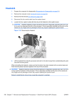
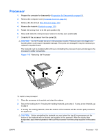
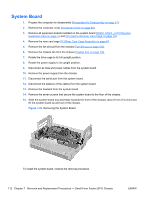
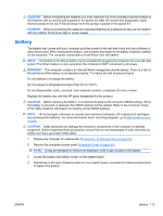
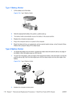
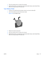
System Board 1. Prepare the computer for disassembly (Preparation for Disassembly on page 61). 2. Remove the computer cover (Computer Cover on page 64). 3. Remove all expansion boards installed on the system board (ADD2, SDVO, or PCI Express Expansion Card on page 75 and PCI Card in the Riser Card Cage on page 78). 4. Remove the riser card cage PCI Riser Card Cage Assembly on page 85. 5. Remove the fan shroud from the chassis (Fan Shroud on page 103). 6. Remove the chassis fan from the chassis Chassis Fan on page 104 7. Rotate the drive cage to its full upright position. 8. Rotate the power supply to its upright position. 9. Disconnect all data and power cables from the system board. 10. Remove the power supply from the chassis. 11. Disconnect the serial port from the system board. 12. Disconnect the balance of the cables from the system board. 13. Remove the heatsink from the system board. 14. Remove the seven screws that secure the system board to the floor of the chassis. 15. Slide the system board tray assembly towards the front of the chassis, about 6 mm (1/4 inch) and lift the system board up and out of the chassis. Figure 7-59 Removing the System Board To install the system board, reverse the removal procedure. 112 Chapter 7 Removal and Replacement Procedures - Small Form Factor (SFF) Chassis ENWW
-
 1
1 -
2
-
3
-
4
-
5
-
6
-
7
-
8
-
9
-
10
-
11
-
12
-
13
-
14
-
15
-
16
-
17
-
18
-
19
-
20
-
21
-
22
-
23
-
24
-
25
-
26
-
27
-
28
-
29
-
30
-
31
-
32
-
33
-
34
-
35
-
36
-
37
-
38
-
39
-
40
-
41
-
42
-
43
-
44
-
45
-
46
-
47
-
48
-
49
-
50
-
51
-
52
-
53
-
54
-
55
-
56
-
57
-
58
-
59
-
60
-
61
-
62
-
63
-
64
-
65
-
66
-
67
-
68
-
69
-
70
-
71
-
72
-
73
-
74
-
75
-
76
-
77
-
78
-
79
-
80
-
81
-
82
-
83
-
84
-
85
-
86
-
87
-
88
-
89
-
90
-
91
-
92
-
93
-
94
-
95
-
96
-
97
-
98
-
99
-
100
-
101
-
102
-
103
-
104
-
105
-
106
-
107
-
108
-
109
-
110
-
111
-
112
-
113
-
114
-
115
-
116
-
 117
117 -
 118
118 -
 119
119 -
 120
120 -
 121
121 -
 122
122 -
 123
123 -
 124
124 -
 125
125 -
 126
126 -
 127
127 -
128
-
129
-
130
-
131
-
132
-
133
-
134
-
135
-
136
-
137
-
138
-
139
-
140
-
141
-
142
-
143
-
144
-
145
-
146
-
147
-
148
-
149
-
150
-
151
-
152
-
153
-
154
-
155
-
156
-
157
-
158
-
159
-
160
-
161
-
162
-
163
-
164
-
165
-
166
-
167
-
168
-
169
-
170
-
171
-
172
-
173
-
174
-
175
-
176
-
177
-
178
-
179
-
180
-
181
-
182
-
183
-
184
-
185
-
186
-
187
-
188
-
189
-
190
-
191
-
192
-
193
-
194
-
195
-
196
 |
 |