HP Rp5700 HP rp5700 Business System Service Reference Guide, 1st Edition - Page 78
Cable Connections
 |
UPC - 884420470731
View all HP Rp5700 manuals
Add to My Manuals
Save this manual to your list of manuals |
Page 78 highlights
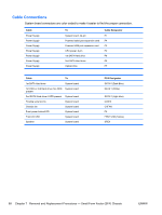
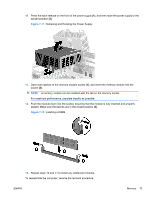
Cable Connections System board connectors are color-coded to make it easier to find the proper connection. Cable Power Supply Power Supply Power Supply Power Supply Power Supply Power Supply Power Supply To System board, 24-pin Powered serial port expansion card Powered USB port expansion card CPU power, 6-pin 1st SATA Hard drive 2nd SATA Hard drive Optical drive Cable Designator P1 P4 P3 P2 P6 P5 P7 Cable To 1st SATA Hard drive System board 1st ODD or 2nd Hard drive if no ODD System board present 2nd SATA Hard drive if ODD present System board Floating serial port A System board Chassis fan System board Front power button/LED System board Front I/O USB System board Speaker System board PCA Designator SATA 0 (Dark Blue) SATA 1 (White) SATA 2 (Light blue) COM 2 CHFAN P5 FRNT USB (Yellow) SPEK 68 Chapter 7 Removal and Replacement Procedures - Small Form Factor (SFF) Chassis ENWW
-
 1
1 -
2
-
3
-
4
-
5
-
6
-
7
-
8
-
9
-
10
-
11
-
12
-
13
-
14
-
15
-
16
-
17
-
18
-
19
-
20
-
21
-
22
-
23
-
24
-
25
-
26
-
27
-
28
-
29
-
30
-
31
-
32
-
33
-
34
-
35
-
36
-
37
-
38
-
39
-
40
-
41
-
42
-
43
-
44
-
45
-
46
-
47
-
48
-
49
-
50
-
51
-
52
-
53
-
54
-
55
-
56
-
57
-
58
-
59
-
60
-
61
-
62
-
63
-
64
-
65
-
66
-
67
-
68
-
69
-
70
-
71
-
72
-
 73
73 -
 74
74 -
 75
75 -
 76
76 -
 77
77 -
 78
78 -
 79
79 -
 80
80 -
 81
81 -
 82
82 -
 83
83 -
84
-
85
-
86
-
87
-
88
-
89
-
90
-
91
-
92
-
93
-
94
-
95
-
96
-
97
-
98
-
99
-
100
-
101
-
102
-
103
-
104
-
105
-
106
-
107
-
108
-
109
-
110
-
111
-
112
-
113
-
114
-
115
-
116
-
117
-
118
-
119
-
120
-
121
-
122
-
123
-
124
-
125
-
126
-
127
-
128
-
129
-
130
-
131
-
132
-
133
-
134
-
135
-
136
-
137
-
138
-
139
-
140
-
141
-
142
-
143
-
144
-
145
-
146
-
147
-
148
-
149
-
150
-
151
-
152
-
153
-
154
-
155
-
156
-
157
-
158
-
159
-
160
-
161
-
162
-
163
-
164
-
165
-
166
-
167
-
168
-
169
-
170
-
171
-
172
-
173
-
174
-
175
-
176
-
177
-
178
-
179
-
180
-
181
-
182
-
183
-
184
-
185
-
186
-
187
-
188
-
189
-
190
-
191
-
192
-
193
-
194
-
195
-
196
 |
 |