HP Rp5700 HP rp5700 Business System Service Reference Guide, 1st Edition - Page 116
Front USB Connector
 |
UPC - 884420470731
View all HP Rp5700 manuals
Add to My Manuals
Save this manual to your list of manuals |
Page 116 highlights
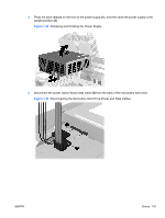
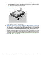
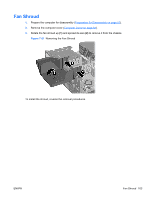
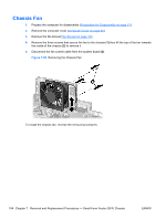
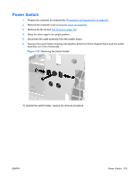
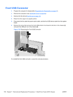
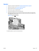
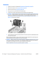
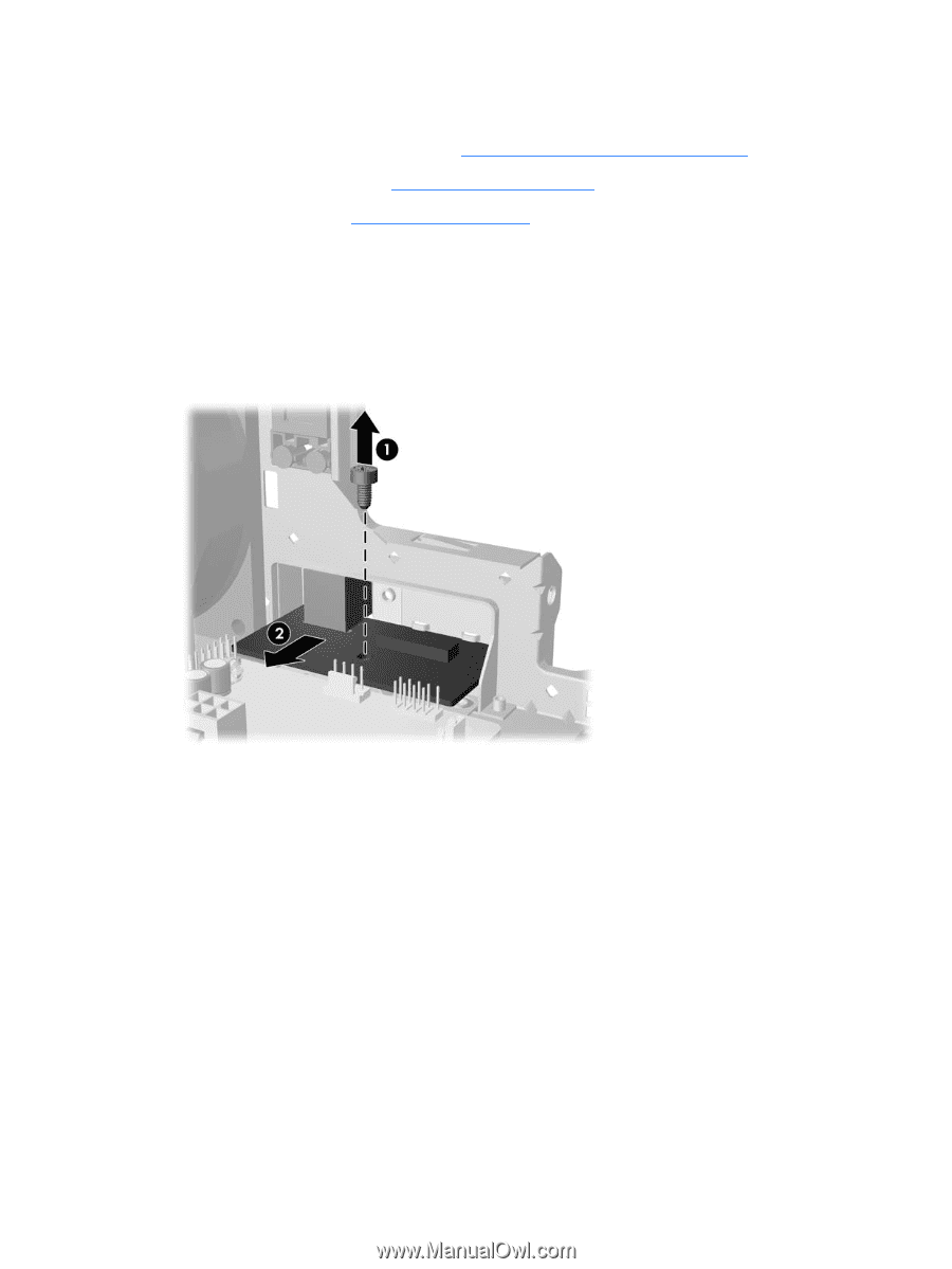
Front USB Connector 1. Prepare the computer for disassembly (Preparation for Disassembly on page 61). 2. Remove the computer cover (Computer Cover on page 64). 3. Remove the fan shroud Fan Shroud on page 103. 4. Raise the drive cage to its upright position. 5. Disconnect the fan cable the power switch cable, and the front USB device cable from the system board. 6. Remove the screw that secures the front USB printed circuit board to the floor of the chassis (1) and push the USB port out of the chassis (2). Figure 7-54 Removing the Front USB Connector To reinstall the front USB connector, reverse the removal procedure. 106 Chapter 7 Removal and Replacement Procedures - Small Form Factor (SFF) Chassis ENWW
-
 1
1 -
2
-
3
-
4
-
5
-
6
-
7
-
8
-
9
-
10
-
11
-
12
-
13
-
14
-
15
-
16
-
17
-
18
-
19
-
20
-
21
-
22
-
23
-
24
-
25
-
26
-
27
-
28
-
29
-
30
-
31
-
32
-
33
-
34
-
35
-
36
-
37
-
38
-
39
-
40
-
41
-
42
-
43
-
44
-
45
-
46
-
47
-
48
-
49
-
50
-
51
-
52
-
53
-
54
-
55
-
56
-
57
-
58
-
59
-
60
-
61
-
62
-
63
-
64
-
65
-
66
-
67
-
68
-
69
-
70
-
71
-
72
-
73
-
74
-
75
-
76
-
77
-
78
-
79
-
80
-
81
-
82
-
83
-
84
-
85
-
86
-
87
-
88
-
89
-
90
-
91
-
92
-
93
-
94
-
95
-
96
-
97
-
98
-
99
-
100
-
101
-
102
-
103
-
104
-
105
-
106
-
107
-
108
-
109
-
110
-
 111
111 -
 112
112 -
 113
113 -
 114
114 -
 115
115 -
 116
116 -
 117
117 -
 118
118 -
 119
119 -
 120
120 -
 121
121 -
122
-
123
-
124
-
125
-
126
-
127
-
128
-
129
-
130
-
131
-
132
-
133
-
134
-
135
-
136
-
137
-
138
-
139
-
140
-
141
-
142
-
143
-
144
-
145
-
146
-
147
-
148
-
149
-
150
-
151
-
152
-
153
-
154
-
155
-
156
-
157
-
158
-
159
-
160
-
161
-
162
-
163
-
164
-
165
-
166
-
167
-
168
-
169
-
170
-
171
-
172
-
173
-
174
-
175
-
176
-
177
-
178
-
179
-
180
-
181
-
182
-
183
-
184
-
185
-
186
-
187
-
188
-
189
-
190
-
191
-
192
-
193
-
194
-
195
-
196
 |
 |
Front USB Connector
1.
Prepare the computer for disassembly (
Preparation for Disassembly
on page
61
).
2.
Remove the computer cover (
Computer Cover
on page
64
).
3.
Remove the fan shroud
Fan Shroud
on page
103
.
4.
Raise the drive cage to its upright position.
5.
Disconnect the fan cable the power switch cable, and the front USB device cable from the system
board.
6.
Remove the screw that secures the front USB printed circuit board to the floor of the chassis
(1)
and push the USB port out of the chassis
(2)
.
Figure 7-54
Removing the Front USB Connector
To reinstall the front USB connector, reverse the removal procedure.
106
Chapter 7
Removal and Replacement Procedures — Small Form Factor (SFF) Chassis
ENWW