HP Rp5700 HP rp5700 Business System Service Reference Guide, 1st Edition - Page 106
CAUTION, Removing the Optical Drive
 |
UPC - 884420470731
View all HP Rp5700 manuals
Add to My Manuals
Save this manual to your list of manuals |
Page 106 highlights
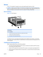
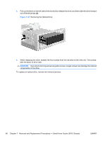
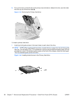
4. Pull out the lever on the left side of the drive (1) to release the drive, and then slide the drive forward out of the drive bay (2). Figure 7-41 Removing the Optical Drive 5. When replacing the drive, transfer the four screws from the old drive to the new one. The screws take the place of drive rails. CAUTION: Use only 5-mm long screws as guide screws. Longer screws can damage the internal components of the drive. To replace an optical drive, reverse the removal process. 96 Chapter 7 Removal and Replacement Procedures - Small Form Factor (SFF) Chassis ENWW
-
 1
1 -
2
-
3
-
4
-
5
-
6
-
7
-
8
-
9
-
10
-
11
-
12
-
13
-
14
-
15
-
16
-
17
-
18
-
19
-
20
-
21
-
22
-
23
-
24
-
25
-
26
-
27
-
28
-
29
-
30
-
31
-
32
-
33
-
34
-
35
-
36
-
37
-
38
-
39
-
40
-
41
-
42
-
43
-
44
-
45
-
46
-
47
-
48
-
49
-
50
-
51
-
52
-
53
-
54
-
55
-
56
-
57
-
58
-
59
-
60
-
61
-
62
-
63
-
64
-
65
-
66
-
67
-
68
-
69
-
70
-
71
-
72
-
73
-
74
-
75
-
76
-
77
-
78
-
79
-
80
-
81
-
82
-
83
-
84
-
85
-
86
-
87
-
88
-
89
-
90
-
91
-
92
-
93
-
94
-
95
-
96
-
97
-
98
-
99
-
100
-
 101
101 -
 102
102 -
 103
103 -
 104
104 -
 105
105 -
 106
106 -
 107
107 -
 108
108 -
 109
109 -
 110
110 -
 111
111 -
112
-
113
-
114
-
115
-
116
-
117
-
118
-
119
-
120
-
121
-
122
-
123
-
124
-
125
-
126
-
127
-
128
-
129
-
130
-
131
-
132
-
133
-
134
-
135
-
136
-
137
-
138
-
139
-
140
-
141
-
142
-
143
-
144
-
145
-
146
-
147
-
148
-
149
-
150
-
151
-
152
-
153
-
154
-
155
-
156
-
157
-
158
-
159
-
160
-
161
-
162
-
163
-
164
-
165
-
166
-
167
-
168
-
169
-
170
-
171
-
172
-
173
-
174
-
175
-
176
-
177
-
178
-
179
-
180
-
181
-
182
-
183
-
184
-
185
-
186
-
187
-
188
-
189
-
190
-
191
-
192
-
193
-
194
-
195
-
196
 |
 |
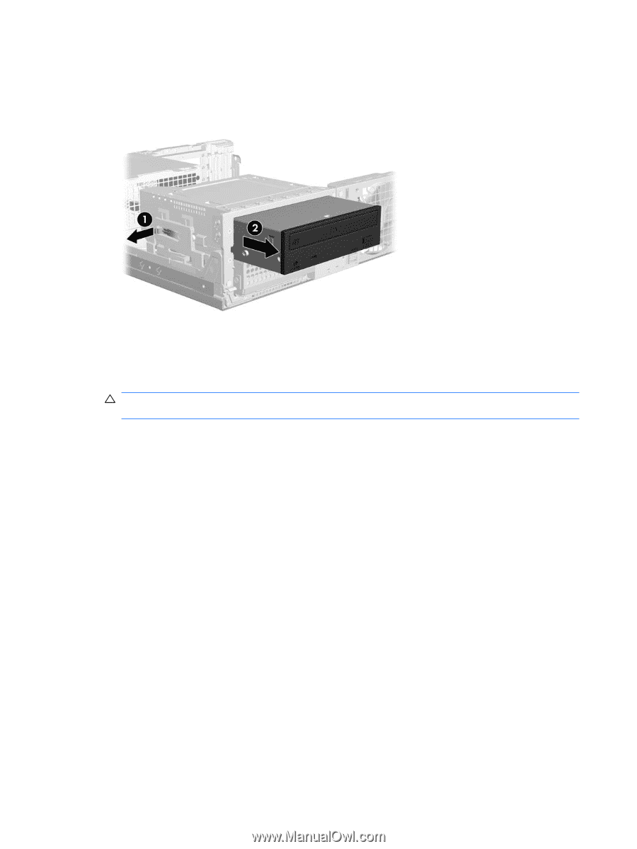
4.
Pull out the lever on the left side of the drive
(1)
to release the drive, and then slide the drive forward
out of the drive bay
(2)
.
Figure 7-41
Removing the Optical Drive
5.
When replacing the drive, transfer the four screws from the old drive to the new one. The screws
take the place of drive rails.
CAUTION:
Use only 5-mm long screws as guide screws. Longer screws can damage the internal
components of the drive.
To replace an optical drive, reverse the removal process.
96
Chapter 7
Removal and Replacement Procedures — Small Form Factor (SFF) Chassis
ENWW