HP StorageWorks 2/140 director product manager user guide - Page 76
Symbols and Indicators, Displaying Port Information, Port Card View, Port Properties, Properties
 |
View all HP StorageWorks 2/140 manuals
Add to My Manuals
Save this manual to your list of manuals |
Page 76 highlights
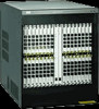
Monitoring and Managing the Director Symbols and Indicators The following figure illustrates the status symbols and LED indicators that may display on a port card in the Port Card View. Figure 2-10: Port Card View 1 UPM 1 An amber LED (at the top of the card) that illuminates if any port fails or blinks if FRU beaconing is enabled. 2 A bank of amber and green LEDs above the ports. One amber LED and one green LED are associated 2 with each port and indicate port status as follows: • The green LED illuminates (or blinks if there is active traffic) and the amber LED extinguishes to indicate normal port operation. • The amber LED illuminates and the green LED extinguishes to indicate a port failure. 3 • Both LEDs extinguish to indicate a port is operational but not communicating with an N_Port (no cable attached, loss of light, port blocked, or link recovery in process). • The amber LED flashes and the green LED either remains on, extinguishes, or flashes to indicate a port is beaconing or running online diagnostics. 3 Four duplex LC connectors for attaching fiber-optic cables. SHR-2274 Refer to the following numbered list for the meaning of the status symbols and LED indicators shown on the Port Card View in Figure 2-10. Port states are described in detail under "Port Operational States" on page 2-41. Displaying Port Information Double-click a port or right-click on a port and choose Port Properties from the menu to display the port's Properties dialog box, as shown in Figure 2-11. Also display this dialog box by: • When you double-click on a row in the Port List View or right-click on a row and choosing Port Properties from the pop-up menu. 2-16 director product manager user guide
-
 1
1 -
2
-
3
-
4
-
5
-
6
-
7
-
8
-
9
-
10
-
11
-
12
-
13
-
14
-
15
-
16
-
17
-
18
-
19
-
20
-
21
-
22
-
23
-
24
-
25
-
26
-
27
-
28
-
29
-
30
-
31
-
32
-
33
-
34
-
35
-
36
-
37
-
38
-
39
-
40
-
41
-
42
-
43
-
44
-
45
-
46
-
47
-
48
-
49
-
50
-
51
-
52
-
53
-
54
-
55
-
56
-
57
-
58
-
59
-
60
-
61
-
62
-
63
-
64
-
65
-
66
-
67
-
68
-
69
-
70
-
 71
71 -
 72
72 -
 73
73 -
 74
74 -
 75
75 -
 76
76 -
 77
77 -
 78
78 -
 79
79 -
 80
80 -
 81
81 -
82
-
83
-
84
-
85
-
86
-
87
-
88
-
89
-
90
-
91
-
92
-
93
-
94
-
95
-
96
-
97
-
98
-
99
-
100
-
101
-
102
-
103
-
104
-
105
-
106
-
107
-
108
-
109
-
110
-
111
-
112
-
113
-
114
-
115
-
116
-
117
-
118
-
119
-
120
-
121
-
122
-
123
-
124
-
125
-
126
-
127
-
128
-
129
-
130
-
131
-
132
-
133
-
134
-
135
-
136
-
137
-
138
-
139
-
140
-
141
-
142
-
143
-
144
-
145
-
146
-
147
-
148
-
149
-
150
-
151
-
152
-
153
-
154
-
155
-
156
-
157
-
158
-
159
-
160
-
161
-
162
-
163
-
164
-
165
-
166
-
167
-
168
-
169
-
170
-
171
-
172
-
173
-
174
-
175
-
176
-
177
-
178
-
179
-
180
-
181
-
182
-
183
-
184
-
185
-
186
-
187
-
188
-
189
-
190
-
191
-
192
-
193
-
194
-
195
-
196
-
197
-
198
-
199
-
200
-
201
-
202
-
203
-
204
-
205
-
206
-
207
-
208
-
209
-
210
-
211
-
212
-
213
-
214
-
215
-
216
-
217
-
218
-
219
-
220
-
221
-
222
-
223
-
224
-
225
-
226
-
227
-
228
-
229
-
230
-
231
-
232
-
233
-
234
-
235
-
236
-
237
-
238
-
239
-
240
-
241
-
242
-
243
-
244
 |
 |
