HP Visualize b180L hp Visualize workstation b132L, b132L plus, b160L, b180L se - Page 133
Installing Memory Modules
 |
View all HP Visualize b180L manuals
Add to My Manuals
Save this manual to your list of manuals |
Page 133 highlights
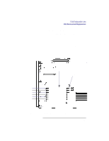
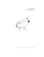
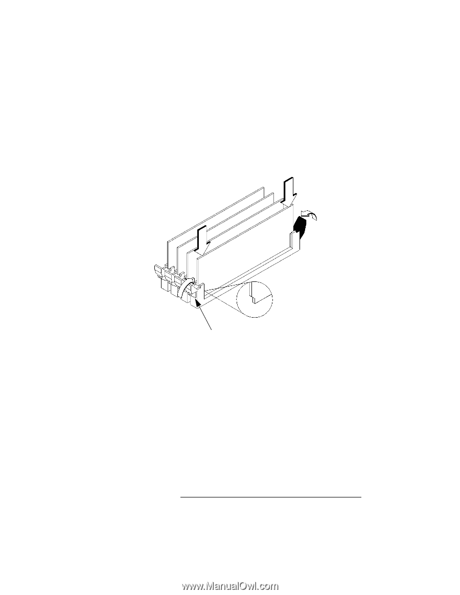
Field Replaceable Units FRU Removal and Replacement 4 Line up the memory module with the guides making sure that the notched end of the memory module is toward the white ejector tabs (front of the main tray), as shown in Figure 25. Figure 25 White Ejector Tab Installing Memory Modules 5 Press firmly and evenly on the memory module to ensure that it is fully seated. 6 To verify that this installation was successful, display the current memory information using the Boot Console Interface. For more information on the Boot Console Interface, see Chapter 9 of this manual. If only a faulty memory module is replaced, use the pdt clear command in the service menu of the Boot Console Interface. Answer y to the prompt Continue? (Y/N). 111
-
 1
1 -
2
-
3
-
4
-
5
-
6
-
7
-
8
-
9
-
10
-
11
-
12
-
13
-
14
-
15
-
16
-
17
-
18
-
19
-
20
-
21
-
22
-
23
-
24
-
25
-
26
-
27
-
28
-
29
-
30
-
31
-
32
-
33
-
34
-
35
-
36
-
37
-
38
-
39
-
40
-
41
-
42
-
43
-
44
-
45
-
46
-
47
-
48
-
49
-
50
-
51
-
52
-
53
-
54
-
55
-
56
-
57
-
58
-
59
-
60
-
61
-
62
-
63
-
64
-
65
-
66
-
67
-
68
-
69
-
70
-
71
-
72
-
73
-
74
-
75
-
76
-
77
-
78
-
79
-
80
-
81
-
82
-
83
-
84
-
85
-
86
-
87
-
88
-
89
-
90
-
91
-
92
-
93
-
94
-
95
-
96
-
97
-
98
-
99
-
100
-
101
-
102
-
103
-
104
-
105
-
106
-
107
-
108
-
109
-
110
-
111
-
112
-
113
-
114
-
115
-
116
-
117
-
118
-
119
-
120
-
121
-
122
-
123
-
124
-
125
-
126
-
127
-
 128
128 -
 129
129 -
 130
130 -
 131
131 -
 132
132 -
 133
133 -
 134
134 -
 135
135 -
 136
136 -
 137
137 -
 138
138 -
139
-
140
-
141
-
142
-
143
-
144
-
145
-
146
-
147
-
148
-
149
-
150
-
151
-
152
-
153
-
154
-
155
-
156
-
157
-
158
-
159
-
160
-
161
-
162
-
163
-
164
-
165
-
166
-
167
-
168
-
169
-
170
-
171
-
172
-
173
-
174
-
175
-
176
-
177
-
178
-
179
-
180
-
181
-
182
-
183
-
184
-
185
-
186
-
187
-
188
-
189
-
190
-
191
-
192
-
193
-
194
-
195
-
196
-
197
-
198
-
199
-
200
-
201
-
202
-
203
-
204
-
205
-
206
-
207
-
208
-
209
-
210
-
211
-
212
-
213
-
214
-
215
-
216
-
217
-
218
-
219
-
220
-
221
-
222
-
223
-
224
-
225
-
226
-
227
-
228
-
229
-
230
-
231
-
232
-
233
-
234
-
235
-
236
-
237
-
238
-
239
-
240
-
241
-
242
 |
 |
Field Replaceable Units
FRU Removal and Replacement
111
4
Line up the memory module with the guides making sure
that the notched end of the memory module is toward the
white ejector tabs (front of the main tray), as shown in
Figure 25.
Figure 25
Installing Memory Modules
5
Press firmly and evenly on the memory module to ensure
that it is fully seated.
6
To verify that this installation was successful, display the
current memory information using the Boot Console In-
terface.
For more information on the Boot Console Interface, see
Chapter 9 of this manual.
If only a faulty memory module is replaced, use the
pdt
clear
command in the service menu of the Boot Console
Interface. Answer
y
to the prompt
Continue? (Y/N)
.
White Ejector Tab